
Owner manual


DS1720
030598 2/12
OPERATION–MEASURING TEMPERATURE
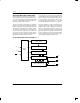
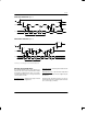
A block diagram of the DS1720 is shown in Figure 1.
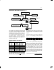
The DS1720 measures temperatures through the use of
an on–board proprietary temperature measurement
technique. A block diagram of the temperature mea-
surement circuitry is shown in Figure 2.
The DS1720 measures temperature by counting the
number of clock cycles that an oscillator with a low tem-
perature coefficient goes through during a gate period
determined by a high temperature coefficient oscillator.
The counter is preset with a base count that corre-
sponds to –55°C. If the counter reaches zero before the
gate period is over, the temperature register, which is
also preset to the –55°C value, is incremented, indicat-
ing that the temperature is higher than –55°C.
At the same time, the counter is then preset with a value
determined by the slope accumulator circuitry. This cir-
cuitry is needed to compensate for the parabolic behav-
ior of the oscillators over temperature. The counter is
then clocked again until it reaches zero. If the gate
period is still not finished, then this process repeats.
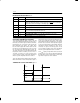
The slope accumulator is used to compensate for the
nonlinear behavior of the oscillators over temperature,
yielding a high resolution temperature measurement.
This is done by changing the number of counts neces-
sary for the counter to go through for each incremental
degree in temperature. To obtain the desired resolution,
therefore, both the value of the counter and the number
of counts per degree C (the value of the slope accumu-
lator) at a given temperature must be known.
DS1720 FUNCTIONAL BLOCK DIAGRAM Figure 1
RST
ADDRESS
AND
RESET
CLK
DQ
STATUS REGISTER AND
CONTROL LOGIC
TEMPERATURE SENSOR
HIGH TEMP TRIGGER, TH
LOW TEMP TRIGGER, TL
DIGITAL COMPARATOR/LOGIC
T
HIGH
T
LOW
T
COM