9-5153; Rev 0; 2/10 SFP Controller with Dual LDD Interface The DS1876 controls and monitors all functions for dual transmitter modules. The memory map is based on SFF-8472. The DS1876 supports APC and modulation control and eye safety functionality for two laser drivers. It continually monitors for high output current, high bias current, and low and high transmit power to ensure that laser shutdown for eye safety requirements are met without adding external components.
DS1876 SFP Controller with Dual LDD Interface TABLE OF CONTENTS Absolute Maximum Ratings . . . . . . . . . . . . . . . . . . . . . . . . . . . . . . . . . . . . . . . . . . . . . . . . . . . . . . . . . . . . . . . . . . . . . . . 5 Recommended Operating Conditions . . . . . . . . . . . . . . . . . . . . . . . . . . . . . . . . . . . . . . . . . . . . . . . . . . . . . . . . . . . . . . . 5 DC Electrical Characteristics . . . . . . . . . . . . . . . . . . . . . . . . . . . . . . . . . . . . . . . . . . . .
SFP Controller with Dual LDD Interface Memory Organization . . . . . . . . . . . . . . . . . . . . . . . . . . . . . . . . . . . . . . . . . . . . . . . . . . . . . . . . . . . . . . . . . . . . . . . . . . 22 Shadowed EEPROM . . . . . . . . . . . . . . . . . . . . . . . . . . . . . . . . . . . . . . . . . . . . . . . . . . . . . . . . . . . . . . . . . . . . . . . . 23 Register Descriptions . . . . . . . . . . . . . . . . . . . . . . . . . . . . . . . . . . . . . . . . . . . . . . . . . . . . . . . . .
DS1876 SFP Controller with Dual LDD Interface LIST OF FIGURES Figure 1. Power-Up Timing . . . . . . . . . . . . . . . . . . . . . . . . . . . . . . . . . . . . . . . . . . . . . . . . . . . . . . . . . . . . . . . . . . . . . . 13 Figure 2. TXD1, TXD2 Timing . . . . . . . . . . . . . . . . . . . . . . . . . . . . . . . . . . . . . . . . . . . . . . . . . . . . . . . . . . . . . . . . . . . . 13 Figure 3. Quick-Trip Sample Timing . . . . . . . . . . . . . . . . . . . . . . . . . . . . . . . . . . . . . . .
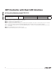
SFP Controller with Dual LDD Interface Continuous Power Dissipation 28-Pin TQFN (derate 34.5mW/°C) above +70°C.....2758.6mW Operating Temperature Range........................... -40NC to +95NC Programming Temperature Range........................ 0NC to +95NC Storage Temperature Range............................. -55NC to +125NC Soldering Temperature.......................... Refer to the IPC/JEDEC J-STD-020 Specification. *Subject to not exceeding +6V.
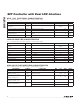
DS1876 SFP Controller with Dual LDD Interface MOD_, APC_ ELECTRICAL CHARACTERISTICS (VCC = +2.85V to +3.9V, TA = -40NC to +95NC, unless otherwise noted.) PARAMETER Main Oscillator Frequency Delta-Sigma Input-Clock Frequency Reference Voltage Input (REFIN) SYMBOL CONDITIONS TYP MAX UNITS 5 MHz fDS fOSC/2 MHz VREFIN Minimum 0.
SFP Controller with Dual LDD Interface (VCC = +2.85V to +3.9V, TA = -40NC to +95NC, unless otherwise noted.) PARAMETER Thermometer Error SYMBOL TERR CONDITIONS MIN TYP -3 -40NC to +95NC MAX UNITS +3 NC MAX UNITS AC ELECTRICAL CHARACTERISTICS (VCC = +2.85V to +3.9V, TA = -40NC to +95NC, unless otherwise noted.
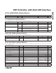
DS1876 SFP Controller with Dual LDD Interface NONVOLATILE MEMORY CHARACTERISTICS (VCC = +2.85V to +3.9V, unless otherwise noted.) PARAMETER EEPROM Write Cycles SYMBOL CONDITIONS MIN At +25NC 200,000 At +85NC 50,000 TYP MAX UNITS All voltages are referenced to ground. Current into the IC is positive, and current out of the IC is negative. Inputs are at supply rail. Outputs are not loaded. This parameter is guaranteed by design. Full scale is user programmable.
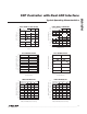
SFP Controller with Dual LDD Interface +95°C 2.5 2.4 2.3 +25°C 2.2 DAC POSITIONS = 1FFh SDA = SCL = VCC 2.9 2.8 SUPPLY CURRENT (mA) SUPPLY CURRENT (mA) DS1876 toc01 SDA = SCL = VCC DACs AT 1FFh 2.6 3.0 -40°C 2.7 VCC = 3.9V 2.6 VCC = 3.3V 2.5 2.4 2.3 2.2 2.1 VCC = 2.85V 2.1 2.0 2.0 2.850 3.150 3.450 -40 3.750 -15 10 35 60 85 TEMPERATURE (°C) VCC (V) APC1/2 AND MOD1/2 DAC DNL APC1/2 AND MOD1/2 DAC INL 0.6 0.4 0.2 0 -0.2 -0.4 -0.6 DS1876 toc04 0.
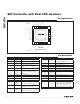
SFP Controller with Dual LDD Interface TXDOUT2 VCC N.C. 20 MOD2 21 GND MOD1 TOP VIEW GND 19 18 17 16 15 REFIN 22 14 BMON1 TXD2 23 13 PMON1 APC2 24 12 BMON2 APC1 25 11 PMON2 VCC 26 10 TXDOUT1 TXF2 27 9 RSEL 8 GND DS1876 *EP 3 4 5 6 7 TXF1 IN1 TXD1 1 RSELOUT 2 TXFOUT OUT1 28 SCL + SDA DS1876 Pin Configuration THIN QFN (5mm × 5mm × 0.8mm) *EXPOSED PAD.
SFP Controller with Dual LDD Interface REFIN VCC VCC SDA SCL MAIN MEMORY EEPROM/SRAM I2C INTERFACE A/D CONFIGURATION/RESULTS, SYSTEM STATUS/CONTROL BITS, ALARMS/WARNINGS, LOOKUP TABLES, USER MEMORY EEPROM 256 BYTES AT A0h VCC MOD2 DAC 10 BITS MOD2 APC2 DAC 10 BITS APC2 MOD1 DAC 10 BITS MOD1 APC1 DAC 10 BITS APC1 13-BIT ADC BMON1 ANALOG MUX PMON1 BMON2 PMON2 TEMPERATURE SENSOR 8-BIT QTs TXFOUT POWER-ON ANALOG INTERRUPT VCC TXD1 TXDOUT1 TXD2 LOGIC CONTROL TXF1 VCC TXDOUT2 TXF2 RSELOUT
DS1876 SFP Controller with Dual LDD Interface Typical Operating Circuit TOSA2 LDD2 BMON APCIN APCSET MODSET FAULT DISABLE TOSA1 LDD1 BMON APCIN APCSET MODSET FAULT DISABLE RC FILTERS (FIGURE 6) MOD1 DAC DS1876 APC1 DAC EEPROM MOD2 DAC APC2 DAC BMON1 PMON1 BMON2 PMON2 RP1 RB1 RP2 TXF1 TXF2 TXFOUT TXDOUT1 TXDOUT2 TXD1 TXD2 TX_FAULT TX_DISABLE1 TX_DISABLE2 QUICK TRIP I2C RB1 SDA SCL MODE_DEF2 (SDA) MODE_DEF1 (SCL) ADC Detailed Description The DS1876 integrates the control and monitoring func
SFP Controller with Dual LDD Interface ACRONYM DESCRIPTION ADC Analog-to-Digital Converter AGC Automatic Gain Control APC Automatic Power Control APD Avalanche Photodiode ATB Alarm Trap Bytes DAC Digital-to-Analog Converter LOS Loss of Signal LUT Lookup Table DACs as a Function of Transmit Disable (TXD1, TXD2) NV Nonvolatile QT Quick Trip TE Tracking Error TIA Transimpedance Amplifier ROSA Shadowed EEPROM SFF Small Form Factor SFP Quick-Trip Timing As shown in Figure 3, the
DS1876 SFP Controller with Dual LDD Interface QT CYCLE QUICK-TRIP SAMPLE TIMES LTXP2 SAMPLE HBIAS1 SAMPLE HBIAS2 SAMPLE HTXP1 SAMPLE HTXP2 SAMPLE LTXP1 SAMPLE LTXP2 SAMPLE HBIAS1 SAMPLE tREP Figure 3. Quick-Trip Sample Timing Table 2. ADC Default Monitor Full-Scale Ranges +FS SIGNAL +FS HEX -FS SIGNAL -FS HEX Temperature (NC) SIGNAL (UNITS) 127.996 7FFF -128 8000 VCC (V) 6.5528 FFF8 0 0000 PMON1, PMON2 and BMON1, BMON2 (V) 2.
SFP Controller with Dual LDD Interface ADC Timing There are six analog channels that are digitized in a round-robin fashion in the order as shown in Figure 4. The total time required to convert all six channels is tRR (see the Analog Voltage Monitoring Characteristics table for details). Right-Shifting ADC Result If the weighting of the ADC digital reading must conform to a predetermined full-scale (PFS) value defined by a standard’s specification (e.g.
DS1876 SFP Controller with Dual LDD Interface SEE RECALL SEE RECALL VPOA VCC VPOD SEE PRECHARGED TO 0 RECALLED VALUE PRECHARGED TO 0 RECALLED VALUE PRECHARGED TO 0 Figure 5. Low-Voltage Hysteresis Example 3.24kΩ 3.24kΩ DAC VOLTAGE OUTPUT 0.01µF 0.01µF DS1876 1kΩ 1kΩ DAC CURRENT SINK 0.1µF 0.1µF 2kΩ DS1876 Figure 6.
SFP Controller with Dual LDD Interface DS1876 O 1 2 3 4 5 6 7 Figure 7. 3-Bit (8-Position) Delta-Sigma Example DAC OFFSET LUTs (04h/06h)[A2h/B2h] EIGHT REGISTERS PER DAC EACH OFFSET REGISTER CAN BE INDEPENDENTLY SET BETWEEN 0 AND 1020. 1020 = 4 x FFh. THIS EXAMPLE ILLUSTRATES POSITIVE TEMPCO.
DS1876 SFP Controller with Dual LDD Interface VCC SET BIAS_ DAC AND MOD_ DAC TO HIGH IMPEDANCE TXDS_ RPU TXD_ C TXDC_ D TXP HI ENABLE TXDIO_ Q C TXP_ HI FLAG TXD_ R FETG_ Q S TXDFG_ TXDOUT_ TXDFLT_ HBAL_ FLAG HBAL ENABLE TXFOUTS_ TXFINT QTHEXT_ TXFOUTS1 TXP_ LO FLAG TXP LO ENABLE TXFOUTS2 INVTXF_ FAULT RESET TIMER (130ms) OUT IN TXDEXT (tINITR1) TXFOUT TXF_ POWER-ON RESET IN OUT TXFS_ NOTE: _ CAN BE EITHER 1 OR 2 CORRESPONDING TO TRANSMITTERS 1 OR 2. REFERS TO A PIN. Figure 9.
SFP Controller with Dual LDD Interface DS1876 DETECTION OF TXFOUT FAULT TXFOUT Figure 11a. TXFOUT Nonlatched Operation DETECTION OF TXFOUT FAULT TXD_ OR TXFOUT RESET TXFOUT Figure 11b. TXFOUT Latched Operation Transmit Fault (TXFOUT) Output TXFOUT can be triggered by all alarms, warnings, QTs, TXD1, TXD2, TXF1, and TXF2 (see Figure 9). The six ADC alarms and warnings are controlled by enable bits (Table 01h/05h, Registers F8h and FCh).
DS1876 SFP Controller with Dual LDD Interface of SCL during a bit read. The device shifts out each bit of data on SDA at the falling edge of the previous SCL pulse and the data bit is valid at the rising edge of the current SCL pulse. Remember that the master generates all SCL clock pulses, including when it is reading bits from the slave. Acknowledgement (ACK and NACK): An acknowledgement (ACK) or not-acknowledge (NACK) is always the 9th bit transmitted during a byte transfer.
SFP Controller with Dual LDD Interface For example: A 3-byte write starts at address 06h and writes three data bytes (11h, 22h, and 33h) to three “consecutive” addresses. The result is that addresses 06h and 07h would contain 11h and 22h, respectively, and the third data byte, 33h, would be written to address 00h. I2C Protocol See Figure 13 for an example of I2C timing.
DS1876 SFP Controller with Dual LDD Interface EEPROM Write Cycles: When EEPROM writes occur, the DS1876 writes the whole EEPROM memory page, even if only a single byte on the page was modified. Writes that do not modify all 8 bytes on the page are allowed and do not corrupt the remaining bytes of memory on the same page. Because the whole page is written, bytes on the page that were not modified during the transaction are still subject to a write cycle.
SFP Controller with Dual LDD Interface I2C ADDRESS A2h/B2h 00h EEPROM (256 BYTES) MAIN DEVICES AT A2h AND B2h AUXILIARY DEVICE LOWER MEMORY PASSWORD ENTRY (PWE) (4 BYTES) TABLE-SELECT BYTE 7Fh 80h 80h ALARMENABLE ROW (8 BYTES) FFh TABLE 06h TABLE 04h (B2h ONLY CONTAINS TRANSMITTER 2RELATED REGISTERS) FFh C7h ALARM-ENABLE ROW CAN BE CONFIGURED TO EXIST AT TABLE 01h OR TABLE 05h USING MASK BIT IN TABLE 02h, REGISTER 88h.
DS1876 SFP Controller with Dual LDD Interface Register Descriptions Memory Map Access Codes The register maps show each byte/word (2 bytes) in terms of its row in the memory. The first byte in the row is located in memory at the row address (hexadecimal) in the leftmost column. Each subsequent byte on the row is one/two memory locations beyond the previous byte/ word’s address. A total of 8 bytes are present on each row.
SFP Controller with Dual LDD Interface LOWER MEMORY ROW (HEX) ROW NAME WORD 0 BYTE 0/8 WORD 1 BYTE 1/9 BYTE 2/A WORD 2 BYTE 3/B BYTE 4/C WORD 3 BYTE 5/D BYTE 6/E BYTE 7/F 00 <1/C> 08 <1/C > THRESHOLD1 VCC ALARM HI VCC ALARM LO VCC WARN HI VCC WARN LO 10 <1/D> THRESHOLD2 BMON ALARM HI BMON ALARM LO BMON WARN HI BMON WARN LO 18 <1/D> THRESHOLD3 THRESHOLD0 TEMP ALARM HI TEMP ALARM LO TEMP WARN HI TEMP WARN LO PMON ALARM HI PMON ALARM LO PMON WARN HI PMON WARN LO 20–40 <
DS1876 SFP Controller with Dual LDD Interface Table 02h Register Map TABLE 02h (PW2) ROW (HEX) ROW NAME WORD 0 WORD 1 WORD 2 WORD 3 BYTE 0/8 BYTE 1/9 BYTE 2/A BYTE 3/B BYTE 4/C BYTE 5/D 80 <0/C> CONFIG0 <8/C>MODE <4/C>TINDEX RESERVED RESERVED RESERVED RESERVED 88 <8/C> CONFIG1 CNFGA CNFGB CNFGC DEVICE ADDRESS RANGING2 RANGING1 BYTE 6/E <10> BYTE 7/F DEVICE ID <10> DEVICE VER RSHIFT2 RSHIFT1 90 <8/C> SCALE0 RESERVED VCC SCALE RESERVED RESERVED 98 <8/C> SCALE1 BMO
SFP Controller with Dual LDD Interface TABLE 05h ROW (HEX) ROW NAME 80–F7 EMPTY F8 <7/M> ALARM ENABLE WORD 0 WORD 1 WORD 2 WORD 3 BYTE 0/8 BYTE 1/9 BYTE 2/A BYTE 3/B BYTE 4/C BYTE 5/D BYTE 6/E EMPTY EMPTY EMPTY EMPTY EMPTY EMPTY EMPTY EMPTY RESERVED RESERVED RESERVED ALARM EN3 RESERVED ALARM EN1 WARN RESERVED EN3 BYTE 7/F or <_/C> = Common, or <_/D> = Different, or <_/M> = Mixture of common and different. Note: Table 05h is empty by default.
DS1876 SFP Controller with Dual LDD Interface Lower Memory Register Descriptions Lower Memory, Register 00h–01h: TEMP ALARM HI Lower Memory, Register 04h–05h: TEMP WARN HI FACTORY DEFAULT 7FFFh READ ACCESS All WRITE ACCESS PW2 or (PW1 and WLOWER) A2h AND B2h MEMORY Common A2h and B2h memory location MEMORY TYPE Nonvolatile (SEE) 00h, 04h S 26 25 24 23 22 21 20 01h, 05h 2-1 2-2 2-3 2-4 2-5 2-6 2-7 2-8 BIT 7 BIT 0 Temperature measurement updates above this two’s complement thres
SFP Controller with Dual LDD Interface DS1876 Lower Memory, Register 08h–09h: VCC ALARM HI Lower Memory, Register 0Ch–0Dh: VCC WARN HI FACTORY DEFAULT FFFFh READ ACCESS All WRITE ACCESS PW2 or (PW1 and WLOWER) A2h AND B2h MEMORY Common A2h and B2h memory location MEMORY TYPE Nonvolatile (SEE) 08h, 0Ch 215 214 213 212 211 210 29 28 09h, 0Dh 27 26 25 24 23 22 21 20 BIT 7 BIT 0 Voltage measurement updates above this unsigned threshold set its corresponding alarm or warning bit.
DS1876 SFP Controller with Dual LDD Interface Lower Memory, Register 10h–11h: BMON ALARM HI Lower Memory, Register 14h–15h: BMON WARN HI Lower Memory, Register 18h–19h: PMON ALARM HI Lower Memory, Register 1Ch–1Dh: PMON WARN HI FACTORY DEFAULT FFFFh READ ACCESS All WRITE ACCESS PW2 or (PW1 and WLOWER) A2h AND B2h MEMORY Different A2h and B2h memory locations MEMORY TYPE Nonvolatile (SEE) 10h, 14h, 18h, 1Ch 215 214 213 212 211 210 29 28 11h, 15h, 19h, 1Dh 27 26 25 24 23 22 21 20
SFP Controller with Dual LDD Interface 20h–47h FACTORY DEFAULT 00h READ ACCESS All WRITE ACCESS PW2 or (PW1 and WLOWER) A2h AND B2h MEMORY Common A2h and B2h memory location MEMORY TYPE Nonvolatile (EE) EE EE EE EE EE DS1876 Lower Memory, Register 20h–47h: EE EE EE BIT 7 EE BIT 0 PW2 level access-controlled EEPROM.
DS1876 SFP Controller with Dual LDD Interface Lower Memory, Register 60h–61h: TEMP VALUE FACTORY DEFAULT 0000h READ ACCESS All WRITE ACCESS N/A A2h AND B2h MEMORY Common A2h and B2h memory location MEMORY TYPE Volatile 60h S 26 25 24 23 22 21 20 61h 2-1 2-2 2-3 2-4 2-5 2-6 2-7 2-8 BIT 7 BIT 0 Signed two’s complement direct-to-temperature measurement.
SFP Controller with Dual LDD Interface DS1876 Lower Memory, Register 64h–65h: BMON VALUE Lower Memory, Register 66h–67h: PMON VALUE POWER-ON VALUE 0000h READ ACCESS All WRITE ACCESS N/A A2h AND B2h MEMORY Different A2h and B2h memory locations MEMORY TYPE Volatile 64h, 66h 215 214 213 212 211 210 29 28 65h, 67h 27 26 25 24 23 22 21 20 BIT 7 BIT 0 Left-justified unsigned voltage measurement.
DS1876 SFP Controller with Dual LDD Interface Lower Memory, Register 6Eh: STATUS Write Access 6Eh POWER-ON VALUE X0XX 0XXXb READ ACCESS All WRITE ACCESS See below A2h AND B2h MEMORY Mixture of common memory locations and different memory locations (see below) MEMORY TYPE Volatile N/A All N/A All All N/A N/A N/A TXDS TXDC IN1S RSELS RSELC TXFS RAM RDYB BIT 7 BIT 0 BIT 7 TXDS1 [A2h]: TXD1 status bit. Reflects the logic state of the TXD1 pin (read-only).
SFP Controller with Dual LDD Interface 6Fh POWER-ON VALUE 00h READ ACCESS All WRITE ACCESS All and DS1876 hardware A2h AND B2h MEMORY Different A2h and B2h memory locations MEMORY TYPE Volatile TEMP RDY VCC RDY BIT 7 BMON RDY PMON RDY RESERVED DS1876 Lower Memory, Register 6Fh: UPDATE RESERVED RESERVED RESERVED BIT 0 BITS 7:4 TEMP RDY, VCC RDY, BMON RDY, PMON RDY: Update of completed conversions. At power-on, these bits are cleared and are set as each conversion is completed.
DS1876 SFP Controller with Dual LDD Interface Lower Memory, Register 70h: ALARM3 70h POWER-ON VALUE 10h READ ACCESS All WRITE ACCESS N/A A2h AND B2h MEMORY Different A2h and B2h memory locations MEMORY TYPE Volatile TEMP HI TEMP LO VCC HI VCC LO BMON HI BMON LO PMON HI BIT 7 PMON LO BIT 0 BIT 7 TEMP HI: High alarm status for temperature measurement. 0 = (default) Last measurement was equal to or below threshold setting. 1 = Last measurement was above threshold setting.
SFP Controller with Dual LDD Interface 71h POWER-ON VALUE 00h READ ACCESS All WRITE ACCESS N/A A2h AND B2h MEMORY Mixed A2h and B2h memory locations MEMORY TYPE Volatile RESERVED RESERVED RESERVED RESERVED RESERVED DS1876 Lower Memory, Register 71h: ALARM2 TXFOUTS FETG BIT 7 BITS 7:3 TXFINT BIT 0 RESERVED BIT 2 TXFOUTS: TXFOUT status. Indicates the state the open-drain output is attempting to achieve. 0 = TXFOUT is pulling low. 1 = TXFOUT is high impedance.
DS1876 SFP Controller with Dual LDD Interface Lower Memory, Register 73h: RESERVED POWER-ON VALUE READ ACCESS N/A WRITE ACCESS N/A A2h AND B2h MEMORY N/A MEMORY TYPE N/A This register is reserved.
SFP Controller with Dual LDD Interface DS1876 Lower Memory, Registers 75h–7Ah: RESERVED MEMORY POWER-ON VALUE READ ACCESS N/A WRITE ACCESS N/A A2h AND B2h MEMORY N/A MEMORY TYPE N/A These registers are reserved. The value when read is 00h.
DS1876 SFP Controller with Dual LDD Interface Lower Memory, Register 7Fh: TABLE SELECT (TBL SEL) POWER-ON VALUE TBLSELPON (Table 02h, Register C7h) READ ACCESS All WRITE ACCESS All A2h AND B2h MEMORY Different A2h and B2h memory locations MEMORY TYPE Volatile 7Fh 27 26 25 24 23 22 21 BIT 7 20 BIT 0 The upper memory tables of the DS1876 are accessible by writing the desired table value in this register.
SFP Controller with Dual LDD Interface F8h POWER-ON VALUE 00h READ ACCESS PW2 or (PW1 and RWTBL1C) or (PW1 and RTBL1C) WRITE ACCESS PW2 or (PW1 and RWTBL1C) A2h AND B2h MEMORY Mixture of common memory locations and different memory locations (see the descriptions below) MEMORY TYPE Nonvolatile (SEE) TEMP HI TEMP LO VCC HI VCC LO BMON HI BIT 7 BMON LO PMON HI PMON LO BIT 0 Layout is identical to ALARM3 in Lower Memory, Register 70h.
DS1876 SFP Controller with Dual LDD Interface Table 01h, Register F9h: RESERVED POWER-ON VALUE READ ACCESS N/A WRITE ACCESS N/A A2h AND B2h MEMORY N/A MEMORY TYPE N/A This register is reserved.
SFP Controller with Dual LDD Interface FCh POWER-ON VALUE 00h READ ACCESS PW2 or (PW1 and RWTBL1C) or (PW1 and RTBL1C) WRITE ACCESS PW2 or (PW1 and RWTBL1C) A2h AND B2h MEMORY Mixture of common memory locations and different memory locations (see the bit descriptions) MEMORY TYPE Nonvolatile (SEE) TEMP HI TEMP LO VCC HI VCC LO BMON HI BIT 7 BMON LO PMON HI PMON LO BIT 0 Layout is identical to WARN3 in Lower Memory, Register 74h.
DS1876 SFP Controller with Dual LDD Interface Table 01h, Register FDh–FFh: RESERVED POWER-ON VALUE READ ACCESS N/A WRITE ACCESS N/A A2h AND B2h MEMORY N/A MEMORY TYPE N/A These registers are reserved.
SFP Controller with Dual LDD Interface BIT 2 MOD1EN: 0 = MOD1 DAC is writable by the user and the LUT recalls are disabled. This allows the user to interactively test their modules by writing the values for MOD1. The output is updated with the new value at the end of the write cycle. The I2C STOP condition is the end of the write cycle. 1 = (default) Enables automatic control of the LUT for MOD1 DAC.
DS1876 SFP Controller with Dual LDD Interface Table 02h, Register 82h–85h: RESERVED FACTORY DEFAULT READ ACCESS N/A WRITE ACCESS N/A A2h AND B2h MEMORY N/A MEMORY TYPE N/A These registers are reserved. Table 02h, Register 86h: DEVICE ID 86h FACTORY DEFAULT 76h READ ACCESS PW2 or (PW1 and RWTBL2) or (PW1 and RTBL2) WRITE ACCESS N/A MEMORY TYPE ROM 0 1 1 1 0 1 1 BIT 7 0 BIT 0 Hardwired connections to show the device ID.
SFP Controller with Dual LDD Interface 88h FACTORY DEFAULT C0h READ ACCESS PW2 or (PW1 and RWTBL2) or (PW1 and RTBL2) WRITE ACCESS PW2 or (PW1 and RWTBL2) A2h AND B2h MEMORY Common A2h and B2h memory location MEMORY TYPE Nonvolatile (SEE) QTHEXT2 RESERVED QTHEXT1 ASEL MASK INVRSOUT DS1876 Table 02h, Register 88h: CNFGA INVTXFOUT2 INVTXFOUT1 BIT 7 BIT 0 BIT 7 QTHEXT2: QT high extension for transmitter 2. 0 = Disabled.
DS1876 SFP Controller with Dual LDD Interface Table 02h, Register 89h: CNFGB 89h FACTORY DEFAULT 00h READ ACCESS PW2 or (PW1 and RWTBL2) or (PW1 and RTBL2) WRITE ACCESS PW2 or (PW1 and RWTBL2) A2h AND B2h MEMORY Common A2h and B2h memory location MEMORY TYPE Nonvolatile (SEE) IN1C INVOUT1 ALATCH2 QTLATCH2 WLATCH2 ALATCH1 QTLATCH1 WLATCH1 BIT 7 BIT 0 BIT 7 IN1C: IN1 software control bit (see Figure 10). 0 = IN1 pin’s logic controls OUT1 pin.
SFP Controller with Dual LDD Interface 8Ah FACTORY DEFAULT 00h READ ACCESS PW2 or (PW1 and RWTBL2) or (PW1 and RTBL2) WRITE ACCESS PW2 or (PW1 and RWTBL2) A2h AND B2h MEMORY Common A2h and B2h memory location MEMORY TYPE Nonvolatile (SEE) TXDFG2 TXDFLT2 TXDIO2 TXDFG1 TXDFLT1 DS1876 Table 02h, Register 8Ah: CNFGC TXDIO1 RESERVED BIT 7 RESERVED BIT 0 BIT 7 TXDFG2: See Figure 9. 0 = FETG2, an internal signal, has no effect on TXDOUT2.
DS1876 SFP Controller with Dual LDD Interface Table 02h, Register 8Ch: RANGING2 8Ch FACTORY DEFAULT 00h READ ACCESS PW2 or (PW1 and RWTBL2) or (PW1 and RTBL2) WRITE ACCESS PW2 or (PW1 and RWTBL2) A2h AND B2h MEMORY Common A2h and B2h memory location MEMORY TYPE Nonvolatile (SEE) RESERVED HBIAS22 HBIAS21 HBIAS20 RESERVED TXP22 TXP21 BIT 7 TXP20 BIT 0 The upper nibble of this byte controls the full-scale range of the QT monitoring for BMON2.
SFP Controller with Dual LDD Interface 8Dh FACTORY DEFAULT 00h READ ACCESS PW2 or (PW1 and RWTBL2) or (PW1 and RTBL2) WRITE ACCESS PW2 or (PW1 and RWTBL2) A2h AND B2h MEMORY Common A2h and B2h memory location MEMORY TYPE Nonvolatile (SEE) RESERVED HBIAS12 HBIAS11 HBIAS10 RESERVED TXP12 DS1876 Table 02h, Register 8Dh: RANGING1 TXP11 BIT 7 TXP10 BIT 0 The upper nibble of this byte controls the full-scale range of the QT monitoring for BMON1.
DS1876 SFP Controller with Dual LDD Interface Table 02h, Register 8Eh: RIGHT-SHIFT2 (RSHIFT2) FACTORY DEFAULT 00h READ ACCESS PW2 or (PW1 and RWTBL2) or (PW1 and RTBL2) WRITE ACCESS PW2 or (PW1 and RWTBL2) A2h AND B2h MEMORY Common A2h and B2h memory location MEMORY TYPE Nonvolatile (SEE) 8Eh RESERVED BMON22 BMON21 BMON20 RESERVED PMON22 PMON21 BIT 7 PMON20 BIT 0 Allows for right-shifting the final answer of BMON2 and PMON2 voltage measurements.
SFP Controller with Dual LDD Interface DS1876 Table 02h, Register 92h–93h: VCC SCALE Table 02h, Register 94h–97h: RESERVED Table 02h, RegisteR 98h–99h: BMON2 SCALE Table 02h, Register 9Ah–9Bh: PMON2 SCALE Table 02h, Register 9Ch–9Dh: BMON1 SCALE Table 02h, Register 9Eh–9Fh: PMON1 SCALE FACTORY CALIBRATED READ ACCESS PW2 or (PW1 and RWTBL2) or (PW1 and RTBL2) WRITE ACCESS PW2 or (PW1 and RWTBL2) A2h AND B2h MEMORY Common A2h and B2h memory location MEMORY TYPE Nonvolatile (SEE) 92h, 94h, 96h, 98h, 9
DS1876 SFP Controller with Dual LDD Interface Table 02h, Register A2h–A3h: VCC OFFSET Table 02h, Register A4h–A7h: RESERVED Table 02h, Register A8h–A9h: BMON2 OFFSET Table 02h, Register AAh–ABh: PMON2 OFFSET Table 02h, Register ACh–ADh: BMON1 OFFSET Table 02h, Register AEh–AFh: PMON1 OFFSET FACTORY DEFAULT 00h READ ACCESS PW2 or (PW1 and RWTBL2) or (PW1 and RTBL2) WRITE ACCESS PW2 or (PW1 and RWTBL2) A2h AND B2h MEMORY Common A2h and B2h memory location MEMORY TYPE Nonvolatile (SEE) A2h, A4h, A6h
SFP Controller with Dual LDD Interface FACTORY DEFAULT FFFF FFFFh READ ACCESS N/A WRITE ACCESS PW2 MEMORY TYPE Nonvolatile (SEE) DS1876 Table 02h, Register B4h–B7h: PW2 B4h 231 230 229 228 227 226 225 224 B5h 223 222 221 220 219 218 217 216 B6h 215 214 213 212 211 210 29 28 27 26 25 24 23 22 21 B7h BIT 7 20 BIT 0 The PWE value is compared against the value written to this location to enable PW2 access. At power-on, the PWE value is set to all ones.
DS1876 SFP Controller with Dual LDD Interface Table 02h, Register BAh: HTXP2 DAC BAh FACTORY DEFAULT 00h READ ACCESS PW2 or (PW1 and RWTBL2) or (PW1 and RTBL2) WRITE ACCESS (PW2 and QT2EN = 0) or (PW1 and RWTBL2 and QT2EN = 0) A2h AND B2h MEMORY Common A2h and B2h memory location MEMORY TYPE Volatile 27 26 25 24 23 22 21 BIT 7 20 BIT 0 The digital value used for the HTXP2 reference and recalled from Table 06h (Registers E8h–EFh) (transmitter 2) at the adjusted memory address found in T
SFP Controller with Dual LDD Interface BDh FACTORY DEFAULT 00h READ ACCESS PW2 or (PW1 and RWTBL2) or (PW1 and RTBL2) WRITE ACCESS (PW2 and QT1EN = 0) or (PW1 and RWTBL2 and QT1EN = 0) A2h AND B2h MEMORY Common A2h and B2h memory location MEMORY TYPE Volatile 27 26 25 24 23 22 21 BIT 7 DS1876 Table 02h, Register BDh: HBIAS1 DAC 20 BIT 0 The digital value used for the HBIAS1 reference and recalled from Table 06h (Registers E0h–E7h) (transmitter 1) at the adjusted memory address found i
DS1876 SFP Controller with Dual LDD Interface Table 02h, Register C0h: PW_ENA C0h FACTORY DEFAULT 10h READ ACCESS PW2 or (PW1 and RWTBL2) or (PW1 and RTBL2) WRITE ACCESS PW2 or (PW1 and RWTBL2) A2h AND B2h MEMORY Common A2h and B2h memory location MEMORY TYPE Nonvolatile (SEE) RESERVED RWTBL1C RWTBL2 RWTBL1A RWTBL1B WLOWER WAUXA BIT 7 WAUXB BIT 0 BIT 7 RESERVED BIT 6 RWTBL1C: Table 01h or 05h bytes F8–FFh. Table address is dependent on MASK bit (Table 02h, Register 88h).
SFP Controller with Dual LDD Interface C1h FACTORY DEFAULT 03h READ ACCESS PW2 or (PW1 and RWTBL2) or (PW1 and RTBL2) WRITE ACCESS PW2 or (PW1 and RWTBL2) A2h AND B2h MEMORY Common A2h and B2h memory location MEMORY TYPE Nonvolatile (SEE) RWTBL46 RTBL1C RTBL2 RTBL1A RTBL1B WPW1 DS1876 Table 02h, Register C1h: PW_ENB WAUXAU BIT 7 WAUXBU BIT 0 BIT 7 RWTBL46: Tables 04h and 06h. 0 = (default) Read and write access for PW2 only. 1 = Read and write access for PW1 and PW2.
DS1876 SFP Controller with Dual LDD Interface Table 02h, Register C6h: POLARITY C6h FACTORY DEFAULT 0Fh READ ACCESS PW2 or (PW1 and RWTBL2) or (PW1 and RTBL2) WRITE ACCESS PW2 or (PW1 and RWTBL2) A2h AND B2h MEMORY Common A2h and B2h memory location MEMORY TYPE Nonvolatile (SEE) RESERVED RESERVED RESERVED RESERVED MOD2P APC2P MOD1P BIT 7 BITS 7:4 APC1P BIT 0 RESERVED BIT 3 MOD2P: MOD2 DAC polarity. The MOD2 DAC (Table 02h, Registers C8h–C9h) range is 000h–3FFh.
SFP Controller with Dual LDD Interface C7h FACTORY DEFAULT 00h READ ACCESS PW2 or (PW1 and RWTBL2) or (PW1 and RTBL2) WRITE ACCESS PW2 or (PW1 and RWTBL2) A2h AND B2h MEMORY Common A2h and B2h memory location MEMORY TYPE Nonvolatile (SEE) 27 26 25 24 23 22 DS1876 Table 02h, Register C7h: TBLSELPON 21 BIT 7 20 BIT 0 Chooses the initial value for the TBL SEL byte (Lower Memory, Register 7Fh) at power-on.
DS1876 SFP Controller with Dual LDD Interface Table 02h, Register CAh–CBh: APC2 DAC FACTORY DEFAULT 0000h READ ACCESS PW2 or (PW1 and RWTBL2) or (PW1 and RTBL2) WRITE ACCESS (PW2 and APC2EN = 0) or (PW1 and RWTBL2 and APC2EN = 0) A2h AND B2h MEMORY Common A2h and B2h memory location MEMORY TYPE Volatile CAh 0 0 0 0 0 0 29 28 CBh 27 26 25 24 23 22 21 20 BIT 7 BIT 0 The digital value used for APC2 DAC.
SFP Controller with Dual LDD Interface FACTORY DEFAULT 0000h READ ACCESS PW2 or (PW1 and RWTBL2) or (PW1 and RTBL2) WRITE ACCESS (PW2 and APC1EN = 0) or (PW1 and RWTBL2 and APC1EN = 0) A2h AND B2h MEMORY Common A2h and B2h memory location MEMORY TYPE Volatile DS1876 Table 02h, Register CEh–CFh: APC1 DAC CEh 0 0 0 0 0 0 29 28 CFh 27 26 25 24 23 22 21 20 BIT 7 BIT 0 The digital value used for APC1 DAC.
DS1876 SFP Controller with Dual LDD Interface Table 04h Register Descriptions Table 04h, Register 80h–C7h: MODULATION LUT (MOD) 80h–C7h FACTORY DEFAULT 00h READ ACCESS PW2 or (PW1 and RWTBL46) WRITE ACCESS PW2 or (PW1 and RWTBL46) A2h AND B2h MEMORY Different A2h and B2h memory locations MEMORY TYPE Nonvolatile (EE) 27 26 25 24 23 22 21 BIT 7 20 BIT 0 Digital value for the MOD1 DAC (A2h address) and MOD2 DAC (B2h address) outputs.
SFP Controller with Dual LDD Interface F8h–FFh FACTORY DEFAULT 00h READ ACCESS PW2 or (PW1 and RWTBL46) WRITE ACCESS PW2 or (PW1 and RWTBL46) A2h AND B2h MEMORY Different A2h and B2h memory locations MEMORY TYPE Nonvolatile (EE) 29 28 27 26 25 DS1876 Table 04h, Register F8h–FFh: MOD OFFSET LUT 24 23 BIT 7 22 BIT 0 The digital value for the temperature offset of the MOD1 and MOD2 DAC outputs.
DS1876 SFP Controller with Dual LDD Interface Table 06h, Register C8h–DFh: EMPTY FACTORY DEFAULT 00h READ ACCESS N/A WRITE ACCESS N/A A2h AND B2h MEMORY N/A MEMORY TYPE None These registers do not exist.
SFP Controller with Dual LDD Interface E8h–EFh FACTORY DEFAULT 00h READ ACCESS PW2 or (PW1 and RWTBL46) WRITE ACCESS PW2 or (PW1 and RWTBL46) A2h AND B2h MEMORY Different A2h and B2h memory locations MEMORY TYPE Nonvolatile (EE) 27 26 25 24 23 DS1876 Table 06h, Register E8h–EFh: HTXP LUT 22 21 BIT 7 20 BIT 0 The HTXP LUT is used to temperature compensate the transmit power-high QT threshold (TXP HI). The table below shows the range of temperature for each byte’s location.
DS1876 SFP Controller with Dual LDD Interface Table 06h, Register F8h–FFh: APC OFFSET LUT F8h–FFh FACTORY DEFAULT 00h READ ACCESS PW2 or (PW1 and RWTBL46) WRITE ACCESS PW2 or (PW1 and RWTBL46) A2h AND B2h MEMORY Different A2h and B2h memory locations MEMORY TYPE Nonvolatile (EE) 29 28 27 26 25 24 23 BIT 7 22 BIT 0 The digital value for the temperature offset of the APC1 and APC2 DAC outputs.
SFP Controller with Dual LDD Interface DS1876 Auxiliary Memory A0h, Register 80h–FFh: EEPROM 80h–FFh FACTORY DEFAULT 00h READ ACCESS All WRITE ACCESS PW2 or (PW1 and WAUXB) or (WAUXBU) MEMORY TYPE Nonvolatile (EE) 27 26 25 24 23 22 21 BIT 7 20 BIT 0 Accessible with the slave address A0h. Applications Information Package Information Power-Supply Decoupling For the latest package outline information and land patterns, go to www.maxim-ic.com/packages.