
Owner's manual

DS2152
031897 21/79
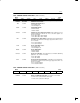
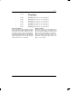
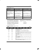
CCR2: COMMON CONTROL REGISTER 2 (Address=38 Hex)
(MSB) (LSB)
TFM TB8ZS TSLC96 TFDL RFM RB8ZS RSLC96 RFDL
SYMBOL POSITION NAME AND DESCRIPTION
TFM CCR2.7 Transmit Frame Mode Select.
0 = D4 framing mode
1 = ESF framing mode
TB8ZS CCR2.6 Transmit B8ZS Enable.
0 = B8ZS disabled
1 = B8ZS enabled
TSLC96 CCR2.5 Transmit SLC–96 / Fs–Bit Insertion Enable. Only set this bit to a one in
D4 framing applications. Must be set to one to source the Fs pattern. See
Section 11 for details.
0 = SLC–96/Fs–bit insertion disabled
1 = SLC–96/Fs–bit insertion enabled
TFDL CCR2.4 Transmit FDL Zero Stuffer Enable. Set this bit to zero if using the internal
HDLC/BOC controller instead of the legacy support for the FDL. See Sec-
tion 11 for details.
0 = zero stuffer disabled
1 = zero stuffer enabled
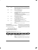
RFM CCR2.3 Receive Frame Mode Select.
0 = D4 framing mode
1 = ESF framing mode
RB8ZS CCR2.2 Receive B8ZS Enable.
0 = B8ZS disabled
1 = B8ZS enabled
RSLC96 CCR2.1 Receive SLC–96 Enable. Only set this bit to a one in D4/SLC–96 framing
applications. See Section 11 for details.
0 = SLC–96 disabled
1 = SLC–96 enabled
RFDL CCR2.0 Receive FDL Zero Destuffer Enable. Set this bit to zero if using the inter-
nal HDLC/BOC controller instead of the legacy support for the FDL. See
Section 11 for details.
0 = zero destuffer disabled
1 = zero destuffer enabled
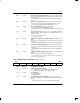
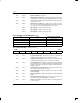
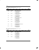
CCR3: COMMON CONTROL REGISTER 3 (Address=30 Hex)
(MSB) (LSB)
ESMDM ESR RLOSF RSMS PDE ECUS TLOOP –
SYMBOL POSITION NAME AND DESCRIPTION
ESMDM CCR3.7 Elastic Store Minimum Delay Mode. See Section 10.3 for details.
0 = elastic stores operate at full two frame depth
1 = elastic stores operate at 32–bit depth