
Instruction Manual


DS2406
2 of 31
ADDRESSABLE SWITCH DESCRIPTION
The DS2406 Dual Addressable Switch™ Plus Memory offers a simple way to remotely control a pair of
open drain transistors and to monitor the logic level at each transistor’s output via the 1-Wire bus for
closed loop control. Each DS2406 has its own 64-bit ROM registration number that is factory lasered into
the chip to provide a guaranteed unique identity for absolute traceability. The device’s 1024 bits of
EPROM can be used as electronic label to store information such as switch function, physical location,
and installation date. Communication with the DS2406 follows the standard Dallas Semiconductor
1-Wire protocol and can be accomplished with minimal hardware such as a single port pin of a
microcontroller. Multiple DS2406 devices can reside on a common 1-Wire network and be operated
independently of each other. Individual devices will respond to a Conditional Search command if they
qualify for certain user-specified conditions, which include the state of the output transistor, the static
logic level or a voltage transition at the transistor’s output.
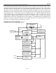
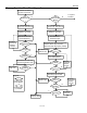
DS2406 BLOCK DIAGRAM Figure 1
64-BIT
LASERED ROM
PROGRAM
VOLTAGE
DETECT
MEMORY
FUNCTION
CONTROL
CRC16
GENERATOR
PARASITE POWER
INT VDD
DATA
8-BIT
SCRATCHPAD
PIO-A
PIO-B
PIO
CONTROL
STATUS MEMORY
5 BYTES EPROM
1 BYTE SRAM
1-WIRE BUS
DATA MEMORY
1024-BIT EPROM
(4 PAGES OF
32 BYTES EACH)
1-WIRE
FUNCTION
CONTROL
V
CC