
Owner's manual


DS2705: SHA-1 Authentication Master
13 of 18
MEMORY
The DS2705 has a 256 byte linear memory space for the EEPROM memory block that stores the challenge,
response and configuration parameters. Addresses designated as “Reserved” typically return FFh when read.
These bytes should not be written. EEPROM memory consists of non-volatile EEPROM cells overlaying volatile
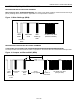
shadow RAM. The Read Data and Write Data protocols allow the 1-Wire interface to directly accesses the shadow
RAM. The Copy Data and Recall Data function commands transfer data between the EEPROM cells and the
shadow RAM. In order to modify the data stored in the EEPROM cells, data must be written to the shadow RAM
and then copied to the EERPOM. In order to verify the data stored in the EEPROM cells, the EEPROM data must
be recalled to the shadow RAM and then read from the shadow. After issuing the Copy Data function command, a
programming pulse is required on the VPP pin.
Figure 5. EEPROM Access via Shadow RAM
Table 6. Memory Map
ADDRESS (HEX) DESCRIPTION READ/WRITE
00 to 07 64-bit Challenge R/W
08 to 1B 160-bit Response (Local MAC) R/W
1C to 1D Configuration Register R/W
1E to FF Reserved —
1-Wire BUS SYSTEM
The 1-Wire bus is a system that has a single bus master and one or more slaves. A multidrop bus is a 1-Wire bus
with multiple slaves, while a single-drop bus has only one slave device. The DS2705 acts as a bus master on the
MDQ pin and as a slave device on the SDQ pin. In both cases, the DS2705 requires a single-drop bus
configuration. The discussion of the 1-Wire bus system consists of three topics: hardware configuration, transaction
sequence, and 1-Wire signaling.
HARDWARE CONFIGURATION
Because the 1-Wire bus has only a single line, it is important that each device on the bus be able to drive it at the
appropriate time. To facilitate this, each device attached to the 1-Wire bus must connect to the bus with open-drain
or tri-state output drivers. The DS2705 uses an open-drain output driver as part of the bidirectional interface
circuitry shown in Figure 6. If a bidirectional pin is not available to act as the bus master when communicating with
the DS2705 as a slave on the SDQ pin, separate output and input pins can be connected together.
The 1-Wire bus must have a pullup resistor at the bus-master end of the bus. The DS2705 internally provides the
pullup for communication as a master on the MDQ pin. The bus master communicating with the DS2705 on SDQ is
responsible for providing an external pullup . The idle state for the 1-Wire bus is high. If, for any reason, a bus
transaction must be suspended, the bus must be left in the idle state to properly resume the transaction later. Note
that if the bus is left low for more than t
LOW0
, slave devices on the bus begin to interpret the low period as a reset
pulse, which effectively terminates the transaction.
Serial
Interface
Write
Read
Shadow RAM
EEPROM
Copy
Recall