
Owner's manual


DS2705: SHA-1 Authentication Master
14 of 18
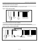
Figure 6. 1-Wire Bus Interface Circuitry, DS2705 as Slave
Vpullup
(2.5 to 5.5V)
Rx
Tx
Rx
Rx = Receive
Tx = Transmit
~100 Ohm
MOSFET
Test System Bus
Master
DS2705 SDQ Port
1.5kW - 4.7kW
(approx.)
Tx
~1 uA
SDQ
TRANSACTION SEQUENCE
The protocol for 1-Wire communication is as follows:
§ Initialization
§ Net Address Command
§ Function Command(s)
§ Data Transfer (not all commands have data transfer)
All transactions of the 1-Wire bus begin with an initialization sequence consisting of a reset pulse transmitted by the
bus master, followed by a presence pulse transmitted by a slave if it is present on the bus. The presence pulse tells
the bus master that a slave device is on the bus and ready to operate. For more details, see the 1-Wire Signaling
section.
NET ADDRESS COMMANDS
Once the bus master has detected the presence of a slave, it can issue the net address command described in the
following paragraph. The name of the Net Address command (ROM command) is followed by its 8-bit opcode in
square brackets.
Skip Net Address [CCh]. The only net address command supported by the DS2705 is the Skip Net Address
command. It is preserved on the DS2705 for compatibility with multidrop enabled slaves such as the DS2703/4.
Skip Net Address must also be used after a reset pulse when a bus master is communicating to the DS2705 over
the SDQ input.
SLAVE PORT (SDQ) FUNCTION COMMANDS
After successfully completing the Skip Net Address command, the bus master can access the features of the
DS2705 with any of the function commands described in the following paragraphs. The name of each function is
followed by the 8-bit opcode for that command in square brackets. The function commands are summarized in
Table 7.
Read Data [69h, XX]. This command reads data starting at memory address XX. The LSb of the data in address
XX is available to be read immediately after the MSb of the address has been entered. Because the address is
automatically incremented after the MSb of each byte is received, the LSb of the data at address XX + 1 is
available to be read immediately after the MSb of the data at address XX. If the bus master continues to read
beyond address FFh, data is read starting at memory address 00 and the address is automatically incremented
until a reset pulse occurs. Addresses labeled “Reserved” in the memory map contain undefined data values. The
read data command can be terminated by the bus master with a reset pulse at any bit boundary. Read Data from
returns the data in the shadow RAM. A Recall Data command is required to transfer data from the EEPROM to the
shadow. See the Memory section for more details.