
Owner's manual


DS2705: SHA-1 Authentication Master
7 of 18
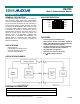
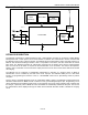
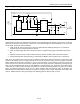
Figure 2. Typical Application Circuit
DS2705
CHAL
PASS
FAIL
Charge Circuit
Charge Supply
VSS
MDQVDD
SDQ
VPP
Charge
Circuit
VSS
Charge
Circuit
VDD
Control
Charge
Circuit
Enable
330 330 1K 150
0.1µF
150
150
150
5.6V 5.6V 18V
VSS
Testpoint
VPP
Testpoint
SDQ
Testpoint
DS2705
Assembly
Programming
Interface
BAT-
Contact
BAT+
Contact
MDQ
Contact
Contacts
from
Charger to
Battery
Pack
BATTERY TOKEN PRESENCE DETECTION
Authentication of a battery or peripheral first depends on the authentication host detecting the presence or insertion
(electrical connection) of the accessory to the host unit. The DS2705 supports insertion detection in four ways, two
use the CHAL pin and two use the MDQ pin:
1. CHAL pin at the active logic level on IC power-up (detected after challenge delay time
t
CHD
). Positive or
negative logic level is determined by the CHP bit.
2. CHAL pin edge trigger after power-up period. Positive or negative edge trigger is determined by the CHP
bit.
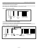
3. Detection of Asynchronous 1-Wire Presence Pulse by insertion of battery with 1-Wire device (token).
4. Periodic Authentication Attempt issuing a 1-Wire Reset on MDQ to test for presence of a 1-Wire token.
With cases 1 and 2 above, the CHAL pin acts as a detection trigger when pulled to a logic low or logic high. A split
contact on the battery ground or supply terminal can be used to connect the CHAL pin to the positive or negative
battery terminal when the battery is present. In case 1, when the battery is connected prior to powering up the host
system (which occurs often since the battery typically powers the host), presence is detected by sensing the logic
level on CHAL immediately after power-up of the DS2705. A configuration bit, CHP, allows the use of either polarity
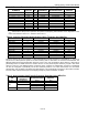
of the CHAL pin. Table 1 shows the timing and sequence of events for detecting presence on power-up. In case 2
above, the DS2705 monitors the CHAL pin for a signal transition after the power-up period is complete. The
DS2705 detects an authentication attempt on a positive or a negative edge of CHAL depending on the state of the
CHP bit. Table 2 shows the timing and sequence of detecting presence with an edge on CHAL.