
Instruction Manual

DS8102
Dual Delta-Sigma Modulator and Encoder
_______________________________________________________________________________________ 3
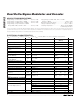
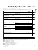
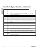
ELECTRICAL CHARACTERISTICS (continued)
(V
DD
= 2.7V to 3.6V, T
A
= -40°C to +85°C, f
CLK
= 8MHz, V
REF
= internal, OSR = 128, unless otherwise noted.) (Note 1)
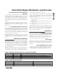
PARAMETER SYMBOL CONDITIONS MIN
TYP
(Note 2)
MAX UNITS
ANALOG-TO-DIGITAL CONVERTER DYNAMIC SPECIFICATIONS
DC Power-Supply Rejection Ratio PSRR
V
DD
= 3.0V to 3.6V, AN0+ = AN0- = AGND,
100mV ripple on V
DD
95 dB
V
DD
= 3.6V, gain = 1, AN0 = 500mV
P-P
,
sinewave at 62.5Hz
70 85
Signal-to-Noise Ratio SINAD
V
DD
= 3.6V, gain = 32, AN0 = 20mV
P-P
,
sinewave at 62.5Hz
70 85
dB
Total Harmonic Distortion
(to 21st Harmonic)
THD
V
DD
= 3.6V, gain = 32, AN0 = 20mV
P-P
,
sinewave at 62.5Hz
-95 -70 dB
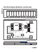
ANALOG-TO-DIGITAL CONVERTER INPUTS
Input Voltage Range AN0+, AN0-, AN1+, and AN1- to AGND -1 +1 V
Gain = 1 1
Gain = 4 4
Gain = 16 16
Input Sampling Capacitance
(Note 1)
C
IN
Gain = 32 32
pF
Input Sampling Rate f
S
Clock at 8MHz (Note 7) 0.667 MHz
Gain = 1 750
Gain = 4 187
Gain = 16 47
Input Impedance to AGND for
8MHz (Note 8)
Gain = 32 23.4
k
Gain = 1 1500
Gain = 4 375
Gain = 16 94
Differential Input Impedance for
8MHz (Note 9)
Gain = 32 46.9
k
Input Bandwidth (-3dB) 7 kHz
External Reference Input Voltage V
REF
1.2 1.25 1.3 V
External Reference Input
Sampling Capacitance
2 pF
Reference Input Sampling Rate f
S
0.67 1 MHz
INTERNAL REFERENCE
Reference Output Voltage 1.24 V
Reference Output Temperature
Coefficient
±30 ppm/°C
Note 1: Specifications to -40°C are guaranteed by design and not production tested.
Note 2: Typical values are not guaranteed. These values are measured at room temperature, V
DD
= 3.3V.
Note 3: These numbers are guaranteed by design and are not tested.
Note 4: Calculated as t
WU1
= 1/f
ICLK
x 8192.
Note 5: Calculated as t
WU2
= 1/f
ICLK
x 57,344.
Note 6: Parameter specifications are based upon the presence of an external cubic sinc filter (as implemented in the MAXQ3108)
for generating full ADC output codewords.
Note 7: f
S
= f
CLK
/12. f
CLK
is the system clock frequency.
Note 8: This is a function of input sampling capacitance (C
IN
) and sampling frequency, and can be approximated as 6/(f
CLK
x C
IN
).
Note 9: Z
IN
(differential) = 2 x Z
IN
(single-ended).