
Instruction Manual

DS8102
Dual Delta-Sigma Modulator and Encoder
_______________________________________________________________________________________ 5
Detailed Description
Operating Modes
The DS8102 has two operating modes: shutdown (or
power-down) mode and active mode.
Shutdown Mode
In shutdown mode, the DS8102 is in an inactive state
and consumes a minimal amount of current. No analog-
to-digital conversion or encoding is performed, and the
internal 8MHz oscillator and internal voltage reference
are disabled.
An integrated power-supply monitor holds the DS8102
in shutdown mode whenever V
DD
≤ V
RST
. Additionally,
the RST pin can be driven low by an external compan-
ion microcontroller (such as the MAXQ3108) to force the
DS8102 to remain in shutdown mode, regardless of the
supply level at V
DD
. This is useful in nonisolated config-
urations (when a power supply is shared between the
DS8102 and the companion microcontroller) to reduce
the current consumption of the entire system. In this
scenario, the companion microcontroller would perform
this sequence of actions when entering stop mode:
1) Drive the RST line on the DS8102 low to force the
DS8102 into shutdown mode.
2) Enter stop mode. Both the companion microcon-
troller and the DS8102 are now in their lowest cur-
rent consumption modes.
3) Exit stop mode.
4) Drive the RST line on the DS8102 high to return the
DS8102 to active mode.
Note: The RST line on the DS8102 does not include
a pullup. This means that if the RST line is not dri-
ven by a companion microcontroller, RST must be
connected to V
DD
for proper operation. RST cannot
be left unconnected.
While the DS8102 is in shutdown mode, the levels on
the configuration input pins (APDREF, CLKSEL, G1,
and G0) can be changed if they are being driven by a
companion microcontroller instead of hardwired to V
DD
or DGND. However, once the DS8102 enters active
mode, the levels on these pins must remain static for
proper operation.
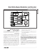
Functional Diagram
DS8102
INTEGRATORS/
COMPARATOR
REFERENCE
BUFFER
DELTA-SIGMA MODULATOR
APDREF
V
REF
AN1+
MNOUT
AN1-
MANCHESTER
ENCODER
POWER
MONITOR
8MHz
OSCILLATOR
INTERNAL
REFERENCE
1x
INTEGRATORS/
COMPARATOR
DELTA-SIGMA MODULATOR
AN0+
AN0-
G1
G0
1x, 4x,
16x, 32x
CLKSEL
CLKIO
RST
V
DD
DGNDAGND