
Manual

DS9502
3 of 3 102199
PHYSICAL SPECIFICATIONS
Size See mechanical drawing
Weight 0.5 grams
ABSOLUTE MAXIMUM RATINGS*
Operating Temperature –40°C to +85°C
Storage Temperature –55°C to +125°C
Soldering Temperature 260°C for 10 seconds
Continuous DC Current Through Package 80 mA
* This is a stress rating only and functional operation of the device at these or any other conditions
above those indicated in the operation sections of this specification is not implied. Exposure to
absolute maximum rating conditions for extended periods of time may affect reliability.
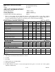
ELECTRICAL CHARACTERISTICS (-40°C to +85°C)
PARAMETER SYMBOL MIN TYP MAX UNITS NOTES
Leakage Current I
L
30 100 nA 2
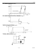
Avalanche Voltage V
AV
7.4 7.8 V 1,3
Trigger Voltage V
TRIGGER
9.0 9.5 V 1
Trigger Current I
TRIGGER
600 1000 mA
Holding Voltage V
HOLD
5.5 V 1
Holding Current I
HOLD
30 mA
Forward Voltage (-10 mA) V
F
-0.7 -0.8 V 4
Forward Current (-0.7V) I
F
-10 -100 mA 4
Maximum Peak Current I
PP
2.0 A 5
Continuous Current Through Diode I
CC
±160
mA 6
CAPACITANCE (t
A
=25°C)
PARAMETER SYMBOL MIN TYP MAX UNITS NOTES
Junction Capacitance (5V) C
J5
55 pF 1
Junction Capacitance (0V) C
J0
100 pF 1
THERMAL RESISTANCE
PARAMETER SYMBOL MIN TYP MAX UNITS NOTES
Junction To Package
R
ΘJC
75 K/W
Junction To Ambient
R
ΘJA
200 K/W
NOTES:
1. All voltages are referenced from Cathode to Anode.
2. At 7.0V.
3. At 0.3 µA.
4. Typical values at room temperature.
5. See pulse specification.
6. In either direction (forward or reverse) through the diode (pins 1 & 6 and 2 & 5 tied together,
otherwise +80 mA max).