GM862-QUAD / PY Hardware User Guide GM862-QUAD-PY, GM862-QUAD HW User Guide 1vv0300748 Rev.
GM862-QUAD / PY Hardware User Guide 1vv0300748 Rev. 5 - 20/09/07 Contents 1 Overview ........................................................................................................................... 6 2 Dimensions ....................................................................................................................... 7 3 Interface connectors on GM862-QUAD / PY .................................................................. 8 3.1 Description ................................
GM862-QUAD / PY Hardware User Guide 1vv0300748 Rev. 5 - 20/09/07 8.1 Microphone Paths Characteristic and Requirements ....................................................... 38 8.2 General Design Rules .......................................................................................................... 41 8.3 Other Considerations ........................................................................................................... 41 8.4 Microphone Biasing .................................
GM862-QUAD / PY Hardware User Guide 1vv0300748 Rev. 5 - 20/09/07 This document is relating to the following products: GM862-QUAD 3 990 250 659 GM862-QUAD-PY 3 990 250 658 Reproduction forbidden without Telit Communications S.p.A.
GM862-QUAD / PY Hardware User Guide 1vv0300748 Rev. 5 - 20/09/07 DISCLAIMER The information contained in this document is the proprietary information of Telit Communications S.p.A. and its affiliates (“TELIT”). The contents are confidential and any disclosure to persons other than the officers, employees, agents or subcontractors of the owner or licensee of this document, without the prior written consent of Telit, is strictly prohibited.
GM862-QUAD / PY Hardware User Guide 1vv0300748 Rev. 5 - 20/09/07 1 Overview The aim of this document is the description of some hardware solutions useful for developing a product with the Telit GM862-QUAD / PY module. In this document all the basic functions of a mobile phone will be taken into account; for each one of them a proper hardware solution will be suggested and eventually the wrong solutions and common errors to be avoided will be evidenced.
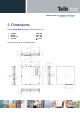
GM862-QUAD / PY Hardware User Guide 1vv0300748 Rev. 5 - 20/09/07 2 Dimensions The Telit GM862-QUAD / PY module overall dimension are: • • • • Length: Width: Thickness: Volume: 43.9 mm 43.9 mm 6.9 mm ≅ 13 cm3 The layout is shown in the following figure: Reproduction forbidden without Telit Communications S.p.A.
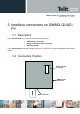
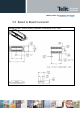
GM862-QUAD / PY Hardware User Guide 1vv0300748 Rev. 5 - 20/09/07 3 Interface connectors on GM862-QUAD / PY 3.1 Description The Telit GM862-QUAD / PY is provided of the following interfaces: • • • GSM antenna connector Board To Board Interface connector SIM Card Reader The Telit GM862-QUAD / PY board to board connector is a CSTP 50 pin vertical SMD Molex 52991–0508 (male). 3.
GM862-QUAD / PY Hardware User Guide 1vv0300748 Rev. 5 - 20/09/07 3.3 Board to Board Connector Molex 52991-0508 (male) GM862 Connector LAY-OUT Reproduction forbidden without Telit Communications S.p.A.
GM862-QUAD / PY Hardware User Guide 1vv0300748 Rev. 5 - 20/09/07 3.3.
GM862-QUAD / PY Hardware User Guide 1vv0300748 Rev. 5 - 20/09/07 Pin Signal 33 C107/DSR 34 GPIO9 35 I/O Function O Internal Pull up Output for Data set ready signal (DSR) to DTE Type CMOS 2.8V I/O Configurable general purpose I/O pin CMOS 2.8V TX_TRACE O RESERVED on GM862-QUAD, Python Debug on GM862-QUAD-PY (TX data) CMOS 2.8V 36 C109/DCD O Output for Data carrier detect signal (DCD) to DTE CMOS 2.8V 37 C104/RXD O Serial data output to DTE CMOS 2.
GM862-QUAD / PY Hardware User Guide 1vv0300748 Rev. 5 - 20/09/07 3.3.2 Antenna Connector The Telit GM862-QUAD / PY includes one 50 Ohm MMCX coaxial female RF connector. On the user application side the following connector must be used: a) Telegärtner MMCX angle plug crimp - Order n. J01340A0121 NOTE: be very careful when connecting the Telit GM862-QUAD/PY RF connector. The RF connector can be damaged if not connected with the proper antenna RF connector.
GM862-QUAD / PY Hardware User Guide 1vv0300748 Rev. 5 - 20/09/07 4 Antenna 4.
GM862-QUAD / PY Hardware User Guide 1vv0300748 Rev. 5 - 20/09/07 4.2 GSM Antenna - Installation Guidelines • • • • Install the antenna in a place covered by the GSM signal. The Antenna must be installed to provide a separation distance of at least 20 cm from all persons and must not be co-located or operating in conjunction with any other antenna or transmitter; Antenna shall not be installed inside metal cases Antenna shall be installed also according Antenna manufacturer instructions. 4.
GM862-QUAD / PY Hardware User Guide 1vv0300748 Rev. 5 - 20/09/07 Current characteristics Level Typical Output Current 1mA Input Current 1uA 4.3.1 Reset signal Signal RESET Function Phone reset I/O I Pin 23 (connector SO301) RESET is used to reset the GM862-QUAD/PY modules. Whenever this signal is pulled low, the GM862 is reset. When the device is reset it stops any operation.
GM862-QUAD / PY Hardware User Guide 1vv0300748 Rev. 5 - 20/09/07 5 Hardware Commands 5.1 Turning ON the GM862-QUAD / PY To turn on the GM862-QUAD / PY the pin ON# must be tied low for at least 1 second and then released. The maximum current that can be drained from the ON# pin is 0,1 mA. A simple circuit to do it is: ON# R1 Q1 Power ON impulse R2 GND NOTE: don't use any pull up resistor on the ON# line, it is internally pulled up.
GM862-QUAD / PY Hardware User Guide 1vv0300748 Rev. 5 - 20/09/07 10k For example: 1- Let's assume you need to drive the ON# pin with a totem pole output of a +3/5 V microcontroller (uP_OUT1): 1s 2- Let's assume you need to drive the ON# pin directly with an ON/OFF button: Reproduction forbidden without Telit Communications S.p.A.
GM862-QUAD / PY Hardware User Guide 1vv0300748 Rev. 5 - 20/09/07 5.2 Turning OFF the GM862-QUAD / PY The turning off of the device can be done in two ways: • by software command (see GM862-QUAD / PY Software User Guide) • by hardware shutdown • by hardware unconditional shutdown When the device is shut down by software command or by hardware shutdown, it issues to the network a detach request that informs the network that the device will not be reachable any more.
GM862-QUAD / PY Hardware User Guide 1vv0300748 Rev. 5 - 20/09/07 5.2.2 Hardware Unconditional Restart To unconditionally Shutdown the GM862-QUAD / PY the pin RESET# must be tied low for at least 200 milliseconds and then released. The maximum current that can be drained from the RESET# pin is 0,15 mA. A simple circuit to do it is: RESET# Unconditional Restart impulse GND NOTE: don't use any pull up resistor on the RESET# line nor any totem pole digital output.
GM862-QUAD / PY Hardware User Guide 1vv0300748 Rev. 5 - 20/09/07 10k For example: 1- Let's assume you need to drive the RESET# pin with a totem pole output of a +3/5 V microcontroller (uP_OUT2): The hardware unconditional restart must not be used during normal operation of the device since it does not detach the device from the network. It shall be kept as an emergency exit procedure to be done in the rare case that the device gets stacked waiting for some network or SIM responses.
GM862-QUAD / PY Hardware User Guide 1vv0300748 Rev. 5 - 20/09/07 6 Power Supply The power supply circuitry and board layout are the most important part in the full product design and they strongly reflect on the product overall performances, hence read carefully the requirements and the guidelines that will follow for a proper design. 6.1 Power Supply Requirements POWER SUPPLY Nominal Supply Voltage 3.8 V Max Supply Voltage 4.2 V Supply voltage range 3.4 V - 4.
GM862-QUAD / PY Hardware User Guide 1vv0300748 Rev. 5 - 20/09/07 If the layout of the PCB is not well designed a strong noise floor is generated on the ground and the supply; this will reflect on all the audio paths producing an audible annoying noise at 216 Hz; if the voltage drop during the peak current absorption is too much, then the device may even shutdown as a consequence of the supply voltage drop.
GM862-QUAD / PY Hardware User Guide 1vv0300748 Rev. 5 - 20/09/07 An example of linear regulator with 5V input is: Reproduction forbidden without Telit Communications S.p.A.
GM862-QUAD / PY Hardware User Guide 1vv0300748 Rev. 5 - 20/09/07 6.2.1.2 + 12V input Source Power Supply Design Guidelines • • • • • • • • The desired output for the power supply is 3.8V, hence due to the big difference between the input source and the desired output, a linear regulator is not suited and shall not be used. A switching power supply will be preferable because of its better efficiency especially with the 2A peak current load represented by the GM862-QUAD / PY.
GM862-QUAD / PY Hardware User Guide 1vv0300748 Rev. 5 - 20/09/07 An example of switching regulator with 12V input is in the below schematic (it is split in 2 parts): Reproduction forbidden without Telit Communications S.p.A.
GM862-QUAD / PY Hardware User Guide 1vv0300748 Rev. 5 - 20/09/07 6.2.1.3 Battery Source Power Supply Design Guidelines • The desired nominal output for the power supply is 3.8V and the maximum voltage allowed is 4.2V, hence a single 3.7V Li-Ion cell battery type is suited for supplying the power to the Telit GM862-QUAD / PY module. The three cells Ni/Cd or Ni/MH 3,6 V Nom.
GM862-QUAD / PY Hardware User Guide 1vv0300748 Rev. 5 - 20/09/07 When the charging current falls below a certain fraction of the fast charge current value, then the battery is considered fully charged, the final charge stops and eventually starts the maintenance. The pulsed charge process has no voltage regulation, instead the charge continues with pulses.
GM862-QUAD / PY Hardware User Guide 1vv0300748 Rev. 5 - 20/09/07 6.2.
GM862-QUAD / PY Hardware User Guide 1vv0300748 Rev. 5 - 20/09/07 6.2.3 Power Supply PCB layout Guidelines As seen on the electrical design guidelines the power supply shall have a low ESR capacitor on the output to cut the current peaks and a protection diode on the input to protect the supply from spikes and polarity inversion. The placement of these components is crucial for the correct working of the circuitry. A misplaced component can be useless or can even decrease the power supply performances.
GM862-QUAD / PY Hardware User Guide 1vv0300748 Rev. 5 - 20/09/07 7 Serial Ports The serial port on the Telit GM862-QUAD / PY is the core of the interface between the module and OEM hardware. 2 serial ports are available on the module: • MODEM SERIAL PORT • TRACE (Usable only on GM862-QUAD-PY for Python Debug) Several configurations can be designed for the serial port on the OEM hardware, but the most common are: • RS232 PC com port • microcontroller UART @ 2.
GM862-QUAD / PY Hardware User Guide 1vv0300748 Rev.
GM862-QUAD / PY Hardware User Guide 1vv0300748 Rev. 5 - 20/09/07 7.1 Level translation In order to interface the Telit GM862-QUAD / PY with a PC com port or a RS232 (EIA/TIA-232) application a level translator is required.
GM862-QUAD / PY Hardware User Guide 1vv0300748 Rev. 5 - 20/09/07 An example of level translation circuitry of this kind is: the RS232 serial port lines are usually connected to a DB9 connector with the following layout: Reproduction forbidden without Telit Communications S.p.A.
GM862-QUAD / PY Hardware User Guide 1vv0300748 Rev. 5 - 20/09/07 7.2 5V UART level translation If the OEM application uses a microcontroller with a serial port (UART) that works at a voltage different from 2.8 - 3V, then a circuitry has to be provided to adapt the different levels of the two set of signals. As for the RS232 translation there are a multitude of single chip translators.
GM862-QUAD / PY Hardware User Guide 1vv0300748 Rev. 5 - 20/09/07 NOTE: The UART input line TXD (rx_uart) of the GM862-QUAD / PY is NOT internally pulled up with a resistor, so there may be the need to place an external 47KΩ pull-up resistor, either the DTR (dtr_uart) and RTS (rts_uart) input lines are not pulled up internally, so an external pull-up resistor of 47KΩ may be required. A power source of the internal interface voltage corresponding to the 2.
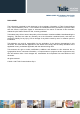
GM862-QUAD / PY Hardware User Guide 1vv0300748 Rev. 5 - 20/09/07 8 Audio Section Overview The Base Band Chip of the GM862-QUAD / PY Telit Module provides two different audio blocks; both in transmit (Uplink) and in receive (Downlink) direction: • • “MT lines” should be used for handset function, “HF lines” is suited for hands -free function (car kit). These two blocks can be active only one at a time, selectable by AXE hardware line or by AT command.
50cm 7cm 3,3mV rms -45dBV/Pa -45dBV/Pa 0,33mV rms 23mVrms 365mV rms GM862-QUAD / PY GE863-GPS Audio Paths Audio Paths +10dB +20dB Ear_HF- Ear_HF+ Mic_HF+ Mic_HF- Ear_MT- Mic_MT- Ear_MT+ GM863-GPS/ GM862-QUAD Mic_MT+ Single ended Balanced Fully Differential Power Buffers Differential Line-Out Drivers 16 -12dBFS 16 audio2.skd 8 GM862-QUAD / PY Hardware User Guide 1vv0300748 Rev. 5 - 20/09/07 EXTERNAL AMPLIFIER Reproduction forbidden without Telit Communications S.p.A.
GM862-QUAD / PY Hardware User Guide 1vv0300748 Rev. 5 - 20/09/07 8.1 Microphone Paths Characteristic and Requirements TIP: being the microphone circuitry the more noise sensitive, its design and layout must be done with particular care. Both microphone paths are balanced and the OEM circuitry should be balanced designed to reduce the common mode noise typically generated on the ground plane. However also an unbalanced circuitry can be used for particular OEM application needs.
GM862-QUAD / PY Hardware User Guide 1vv0300748 Rev. 5 - 20/09/07 (*) WARNING. AC means that the signals from microphone has to be connected to input lines of the module by a CAPACITOR , which value must be ≥ 100nF . Not respecting this constraint, the input stage will be damaged. TIP: definition of the nominal sensitivity of the microphone lines . The nominal sensitivity of the microphone lines indicates the voltage level on the GM862-QUAD / PY pins present during "normal spoken" conditions.
GM862-QUAD / PY Hardware User Guide 1vv0300748 Rev. 5 - 20/09/07 [− 49,7 + 20 + G A ] = −8,76 − 40,9 + 20 = −G A G A = 20,94dB you can set GA= +20dB to use standard resistor values . TIP: environment consideration . For hands-free/car kit microphone, you must take into account the voice attenuation, due to the distance between the microphone itself and the talker, when designing the external microphone amplifier.
GM862-QUAD / PY Hardware User Guide 1vv0300748 Rev. 5 - 20/09/07 Hence in these conditions the signal level on the“Mic_HF” input pads of the GM862-QUAD / PY is 10 dB (3 times) lower than the nominal, as suggested. 8.2 General Design Rules There are several configurations for the audio paths, but the most effective difference is between balanced and unbalanced microphone configuration.
GM862-QUAD / PY Hardware User Guide 1vv0300748 Rev. 5 - 20/09/07 8.4 Microphone Biasing The electret microphones usually need a biasing voltage to work properly. Refer to your microphone provider for the characteristics required. NOTE: The microphones have a hot wire were the positive biasing must be connected. Usually it is indicated by a + symbol or a red point. If the polarity of the bias is reversed, then the microphone will not work properly. For this reason be sure to respect the mic.
GM862-QUAD / PY Hardware User Guide 1vv0300748 Rev. 5 - 20/09/07 NOTE: The cable to the microphone should not be shielded; instead a twisted pair cable shall be used. NOTE: The microphone sensitivity changes with the value of R2 and R3. Usually the microphones are characterized with 2kΩ biasing resistance, so try to keep the sum of R2 and R3 around 2kΩ. Refer to your microphone manufacturer for the mic. characteristics. 8.4.
GM862-QUAD / PY Hardware User Guide 1vv0300748 Rev. 5 - 20/09/07 NOTE: In the unbalanced application the capacitor C3 shall be > 200nF otherwise the frequency response will be cut at low band frequencies (down to 300Hz). This capacitor can be placed close to the MIC- pad (MIC_HF- or MIC_MT- depending on the audio path chosen) or if possible it should be placed close to the shielded cable connector.
GM862-QUAD / PY Hardware User Guide 1vv0300748 Rev. 5 - 20/09/07 8.5 Microphone Buffering As seen previously, a microphone shall be connected to the input pins of the GM862-QUAD / PY through a buffer amplifier that boosts the signal level to the required value. Again the buffered microphone circuitry can be balanced or unbalanced: where possible it is always preferable a balanced solution. The buffering circuit shall be placed close to the microphone or close to the microphone wire connector. 8.5.
GM862-QUAD / PY Hardware User Guide 1vv0300748 Rev. 5 - 20/09/07 The buffer gain is given by the formula: Gain = R604 R606 = R605 R607 The C636 and C637 capacitors are placed in order to cut off the gain at higher frequencies than the transmitted GSM band, the cutoff frequency (-3dB) should be 3500Hz in order to have -1dB at 3kHz. The cutoff frequency is given by the formula: freq. = 1 1 = [Hz] 2π * R604 * C 637 2π * R606 * C 636 TIP: example of calculation.
GM862-QUAD / PY Hardware User Guide 1vv0300748 Rev. 5 - 20/09/07 8.5.2 Buffered Unbalanced (Single Ended) Microphone 2,7nF 6,8nF The above schematic can be used for a single ended (buffered unbalanced) microphone; the required biasing circuitry is not included. Note also that the capacitor C3 is not needed.
GM862-QUAD / PY Hardware User Guide 1vv0300748 Rev. 5 - 20/09/07 The buffer bandwidth at -3dB shall be 4KHz. Note that the biasing of the operational amplifier is given for the inverting amplifier by the series divider R714-R715. The 100nF capacitor C719 is needed to filter the noise that could be coupled to that divider. For the not inverting operational amplifier the biasing is given by a different divider R715-R717 with the capacitor C720 and through a series resistor R718 of 470KΩ.
GM862-QUAD / PY Hardware User Guide 1vv0300748 Rev. 5 - 20/09/07 As a consequence of the assigned values of the resistors, the nominal values of C726 and C727 are: C726= 1/ (2π*4000*R719)= 7.10 *10 -9 F C727= 1/ (2π*4000*R711)= 2,65 *10 -9 F modified in 6,8nF (fc1=4181Hz ) and 2,7nF (fc2=3931Hz) because of commercial values . Reproduction forbidden without Telit Communications S.p.A.
GM862-QUAD / PY Hardware User Guide 1vv0300748 Rev. 5 - 20/09/07 9 OUTPUT LINES (Speaker) 9.1 Short Description The Telit GM862-QUAD / PY provides two audio paths in receive section. Only one of the two paths can be active at a time, selectable by AXE hardware line or by AT command.
GM862-QUAD / PY Hardware User Guide 1vv0300748 Rev. 5 - 20/09/07 9.2 Output Lines Characteristics “Ear_MT” Differential Line-out Drivers Path • line coupling: • line type: • output load resistance : • internal output resistance: • signal bandwidth: • max.
GM862-QUAD / PY Hardware User Guide 1vv0300748 Rev. 5 - 20/09/07 9.
GM862-QUAD / PY Hardware User Guide 1vv0300748 Rev. 5 - 20/09/07 9.4 Handset Earphone Design As seen previously, a 16Ω earpiece can be directly connected to the output pads EAR_MT+ and EAR_MT- of the GM862-QUAD / PY. This solution is often the more cost effective, reducing the components count to a minimum.
GM862-QUAD / PY Hardware User Guide 1vv0300748 Rev. 5 - 20/09/07 The resulting gain and high pass cut can be obtained with the formula: Gain = freq. = R3 R2 1 [Hz] 2π * R3 * C 4 And an example of internal Ear amplifier could be: +12dB GM862-QUAD / PY Some amplifier require a low impedance load at high frequency in order to avoid auto oscillation, this can be made with a capacitor (100nF) in series with a resistor (15Ω).
GM862-QUAD / PY Hardware User Guide 1vv0300748 Rev. 5 - 20/09/07 9.6 Car Kit Speakerphone Design For the car kit speaker phone function the power output requirement is usually at least 4W, therefore an amplifier is needed to boost the GM862-QUAD / PY output. The design of the amplifier shall comply with the following guidelines: • • • • • • The input to the amplifier MUST be taken from the “Ear_HF” audio path of the GM862-QUAD / PY, because of its echo canceller parameters suited to a car cabin use.
GM862-QUAD / PY Hardware User Guide 1vv0300748 Rev. 5 - 20/09/07 10 General Purpose I/O The general purpose I/O pins can be configured to act in three different ways: • input • output • alternate function (internally controlled) The following GPIO are available on the GM862-QUAD/PY: Pin Signal I/O 34 GPI1 I GPI01 Configurable GPIO CMOS 2.8V Input / output current 1uA / 1mA 28 GPO2 O GPO02 Configurable GPIO CMOS 2.
GM862-QUAD / PY Hardware User Guide 1vv0300748 Rev. 5 - 20/09/07 Not all GPIO pins support all these three modes: • GPIO1 is an INPUT ONLY • GPIO2 is an OUTPUT ONLY (open collector) • GPIO3, GPIO8 to GPIO13 support both input or output mode but not Alternate function.
GM862-QUAD / PY Hardware User Guide 1vv0300748 Rev. 5 - 20/09/07 10.1 GPIO Logic levels Where not specifically stated, all the interface circuits work at 2.8V CMOS logic levels. The following table shows the logic level specifications used in the GM862-QUAD/PY interface circuits: Absolute Maximum Ratings -Not Functional Parameter Min Input level on any digital -0.3V pin when on Input voltage on analog -0.3V pins when on Max +3.6V +3.0 V Operating Range - Interface levels (2.
GM862-QUAD / PY Hardware User Guide 1vv0300748 Rev. 5 - 20/09/07 10.2 Using a GPIO pin as INPUT The GPIO pins, when used as inputs, can be connected to a digital output of another device and report its status, provided this device has interface levels compatible with the 2.8V CMOS levels of the GPIO. If the digital output of the device to be connected with the GPIO input pin has interface levels different from the 2.
GM862-QUAD / PY Hardware User Guide 1vv0300748 Rev. 5 - 20/09/07 10.6 Using the Buzzer Output GPIO7 The GPIO7 pin, when configured as Buzzer Output, is controlled by the GM862-QUAD / PY module and will drive with appropriate square waves a Buzzer driver. This permits to your application to easily implement Buzzer feature with ringing tones played at the call incoming, on SMS incoming or simply playing a tone when needed by your application.
GM862-QUAD / PY Hardware User Guide 1vv0300748 Rev. 5 - 20/09/07 11 ADC section 11.1 ADC converter 11.1.1 Description The GM862-QUAD / PY module provides a Analog to Digital Converter. The input line (named ADC_IN1) is available on pin #6 of the B2B connector of the module and on pin #19 of PL103 on EVK2 Board. The on board A/D is 11-bit converter. It is able to read a voltage level in the range of 0÷2 volts applied on the ADC pin input, store and convert it into 11 bit word.
GM862-QUAD / PY Hardware User Guide 1vv0300748 Rev. 5 - 20/09/07 12 Indication of network service availability The STAT_LED pin status shows information on the network service availability and Call status. The pin is an Open Collector output where it is possible to directly connect a LED to show information on the network service availability and Call status. Therefore, the status indicated in the following table is reversed with respect to the pin status.
GM862-QUAD / PY Hardware User Guide 1vv0300748 Rev. 5 - 20/09/07 13 Mounting the GM862 Modules on your Board In order to electrically connect your board to the Telit GM862-QUAD/PY modules, use a CSTP 2x25 pin vertical SMD SCH–SCH Molex 53748 - 0504 (female, low profile) as a counterpart to the CSTP 50 pin vertical SMD Molex 52991–0508 (male) of your Telit GM862-QUAD/PY modules.
GM862-QUAD / PY Hardware User Guide 1vv0300748 Rev. 5 - 20/09/07 NOTE: be very careful when connecting the Telit GM862 module RF connector. The Telit GM862 module RF connector can be damaged if not connected with the proper antenna RF connector. The minimum number of insertion cycles is recommended. 13.
GM862-QUAD / PY Hardware User Guide 1vv0300748 Rev. 5 - 20/09/07 - Angle connector fixing example 2 NOTE: in the examples the cable is always bent, this is not a constrain. If the installation does not require it, then the cable can be kept straight, ensuring that the fixing is without sliding. 13.2 Precautions • • • • • The plug should be inserted in the connector only after the installation of the Telit GM862QUAD/PY in the board.
GM862-QUAD / PY Hardware User Guide 1vv0300748 Rev. 5 - 20/09/07 14 Conformity Assessment Issues The GM862-QUAD & GM862-QUAD-PY module is assessed to be conforming to the R&TTE Directive as stand-alone products so If the module is installed in conformance with Telit Communications installation instructions require no further evaluation under Article 3.2 of the R&TTE Directive and do not require further involvement of a R&TTE Directive Notified Body for the final product.
GM862-QUAD / PY Hardware User Guide 1vv0300748 Rev. 5 - 20/09/07 15 SAFETY RECOMMANDATIONS READ CAREFULLY Be sure the use of this product is allowed in the country and in the environment required.
GM862-QUAD / PY Hardware User Guide 1vv0300748 Rev. 5 - 20/09/07 16 Document Change Log Revision ISSUE#0 ISSUE#1 ISSUE#2 ISSUE#3 ISSUE#4 Date 16/10/06 24/10/06 19/12/06 08/01/07 02/07/07 ISSUE#5 20/09/07 Changes Release First ISSUE# 0 Added chapter 11 (Conformity assessment Issues) Modified 3.3.1, 4.1, 4.2, 4.3, 6.1, 6.2.14 Modified 3.3.