
User Manual


ISD1800 SERIES
Publication Release Date: June 7, 2005
- 7 - Revision 0.3
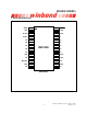
PIN NAME PIN NO. I/O FUNCTION
MIC 10 I
Microphone Input: The microphone input
transfers its signals to the on-chip preamplifier. An
on-chip Automatic Gain Control (AGC) circuit
controls the gain of the preamplifier. An external
microphone should be AC coupled to this pin via
a series capacitor. The capacitor value, together
with an internal 10 K resistance on this pin,
determines the low-frequency cutoff for the
I1800
passband.
MIC REF 12 I
Microphone Reference: The MIC REF input is
the inverting input to the microphone preamplifier.
This provides input noise-cancellation, or
common-mode rejection, when the microphone is
connected differentially to the device.
AGC 13 I
Automatic Gain Control: The AGC dynamically
adjusts the gain of the preamplifier to compensate
for the wide range of microphone input levels. The
AGC allows the full range of sound, from whispers
to loud sounds, to be recorded with minimal
distortion. Nominal values of 4.7 µF give
satisfactory results in most cases.
Connecting this pin to ground (V
SSA
) provides
maximum gain to the preamplifier circuitry.
Conversely, connecting this pin to the power
supply (V
CCA
) provides minimum gain to the
preamplifier circuitry.
SP-/SP+ 15, 17 O
Speaker Outputs: The SP+ and SP- pins provide
direct drive for loudspeakers with impedances as
low as 8. A single output may be used, but, for
direct-drive loud-speakers, the two opposite-
polarity outputs provide an improvement in output
power of up to four times over a single-ended
connection. Furthermore, when SP+ and SP- are
used, a speaker coupling capacitor is not
required. A single-ended connection will require
an AC-coupling capacitor between the SP pin and
the speaker.
The SP+ pin and the SP- pin are internally
connected through a 50 K resistance. When not
in playback mode, they are floating.