
User Manual
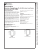
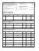
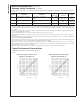
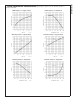
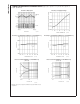
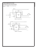

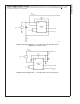
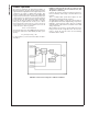
Table Of Contents
- LM3812/LM3813
- General Description
- Key Specifications
- Features
- Applications
- Connection Diagrams
- Ordering Information
- Pin Description (High-Side, LM3812)
- Pin Description (Low-Side, LM3813)
- Absolute Maximum Ratings
- Operating Ratings
- Electrical Characteristics
- Typical Performance Characteristics
- Typical Application Circuits
- FIGURE 1. High Side Sense
- FIGURE 2. Low Side Sense
- FIGURE 3. Paralleling LM3812 for Higher Load Current ITOTAL = 2.2(D1-0.5)IMAX + 2.2(D2-0.5)IMAX
- FIGURE 4. High Voltage Operation - VIN Greater Than 5.25V (High Side Sense) (PWM output is referr
- FIGURE 5. High Voltage Operation - VIN Greater Than 5.25V (Low Side Sense)
- Product Operation
- PWM Output and Current Accuracy
- Look-Up Tables
- TABLE 2. Duty Cycle to Current Conversion Table
- Timing Diagram
- Physical Dimensions
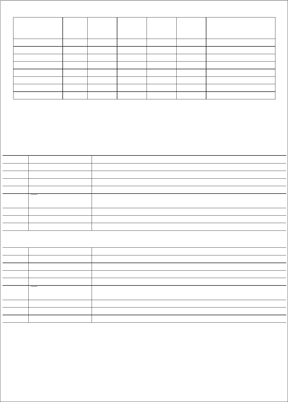
Ordering Information
Order No.
#
Sense
Range
Sampling
Interval*
Sensing
Method
NS
Package
Number
‡
Package
Type Supplied As:
LM3812M-1.0
±
1A 50 ms High-side M08A SO-8 95 units in Rails
LM3812MX-1.0
±
1A 50 ms High-side M08A SO-8 2.5k units on Tape and Reel
LM3812M-7.0
±
7A 50 ms High-side M08A SO-8 95 units in Rails
LM3812MX-7.0
±
7A 50 ms High-side M08A SO-8 2.5k units on Tape and Reel
LM3813M-1.0
±
1A 50 ms Low-side M08A SO-8 95 units in Rails
LM3813MX-1.0
±
1A 50 ms Low-side M08A SO-8 2.5k units on Tape and Reel
LM3813M-7.0
±
7A 50 ms Low-side M08A SO-8 95 units in Rails
LM3813MX-7.0
±
7A 50 ms Low-side M08A SO-8 2.5k units on Tape and Reel
#
Suffix M indicates that the part is available in Surface
Mount package. Suffix X indicates that the part is available in
2.5k units on Tape and Reel.
* Current is sampled over a fixed interval. The average
current during this interval is indicated by the duty cycle of
the PWM output during next interval.
‡
The Package code M08A is internal to National Semicon-
ductor and indicates an 8-lead surface mount package,
SO-8.
Pin Description (High-Side, LM3812)
Pin Name Function
1 SENSE+, V
DD
High side of internal current sense, also supply voltage.
2 SENSE− Low side of internal current sense.
3 FLTR+ Filter input — provides anti-aliasing for delta sigma modulator.
4 FLTR− Filter input.
5SD
Shutdown pin. Connected to V
DD
through a pull up resistor for normal operation. When
low, the IC goes into a low current mode (typically 3 µA).
6 PWM PWM output indicates the current magnitude and direction.
7 GND Ground
8 GND Ground
Pin Description (Low-Side, LM3813)
Pin Name Function
1 SENSE+, GND High side of internal current sense, also ground.
2 SENSE− Low side of internal current sense.
3 FLTR+ Filter input – provides anti-aliasing for delta sigma modulator.
4 FLTR− Filter input.
5SD
Shutdown pin. Connected to V
DD
through a pull up resistor for normal operation. When
low, the IC goes into a low current mode (typically 3 µA).
6 PWM PWM output indicates the current magnitude and direction.
7 GND Ground
8V
DD
V
DD
(supply)
LM3812/LM3813
www.national.com 2