
User guide

1.0 Mounting (Continued)
2.0 Capacitive Loads
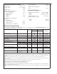
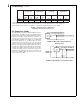
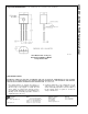
The LM60 handles capacitive loading well. Without any spe-
cial precautions, the LM60 can drive any capacitive load as
shown in
Figure 4
. Over the specified temperature range the
LM60 has a maximum output impedance of 800Ω.Inan
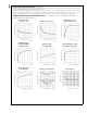
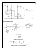
extremely noisy environment it may be necessary to add
some filtering to minimize noise pickup. It is recommended
that 0.1 µF be added from +V
S
to GND to bypass the power
supply voltage, as shown in
Figure 5
. In a noisy environment
it may be necessary to add a capacitor from the output to
ground. A 1 µF output capacitor with the 800Ω output imped-
ance will form a 199 Hz lowpass filter. Since the thermal time
constant of the LM60 is much slower than the 6.3 ms time
constant formed by the RC, the overall response time of the
LM60 will not be significantly affected. For much larger ca-
pacitors this additional time lag will increase the overall
response time of the LM60.
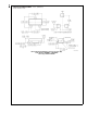
SOT-23
*
SOT-23
**
TO-92
*
TO-92
***
no heat sink small heat fin no heat fin small heat fin
θ
JA
T
J
−T
A
θ
JA
T
J
−T
A
θ
JA
T
J
−T
A
θ
JA
T
J
−T
A
(˚C/W) (˚C) (˚C/W) (˚C)
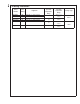
Still air 450 0.17 260 0.1 180 0.07 140 0.05
Moving air 180 0.07 90 0.034 70 0.026
*
-Part soldered to 30 gauge wire.
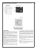
**
-Heat sink used is
1
⁄
2
" square printed circuit board with 2 oz. foil with part attached as shown in
Figure 2
.
***
-Part glued or leads soldered to 1” square of 1/16” printed circuit board with 2 oz. foil or similar.
FIGURE 3. Temperature Rise of LM60 Due to
Self-Heating and Thermal Resistance (θ
JA
)
01268115
FIGURE 4. LM60 No Decoupling Required for
Capacitive Load
01268116
FIGURE 5. LM60 with Filter for Noisy Environment
LM60
www.national.com 6