
User guide

MAX1027/MAX1029/MAX1031
10-Bit 300ksps ADCs with FIFO,
Temp Sensor, Internal Reference
_______________________________________________________________________________________ 5
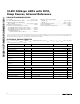
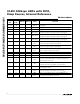
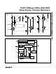
Note 9: This time is defined as the number of clock cycles needed for conversion multiplied by the clock period. If the internal refer-
ence needs to be powered up, the total time is additive. The internal reference is always used for temperature measurements.
PARAMETER SYMBOL CONDITIONS MIN TYP MAX UNITS
Externally clocked conversion 208
SCLK Clock Period t
CP
Data I/O 100
ns
SCLK Duty Cycle t
CH
40 60 %
SCLK Fall to DOUT Transition t
DOT
C
LOAD
= 30pF 40 ns
CS Rise to DOUT Disable t
DOD
C
LOAD
= 30pF 40 ns
CS Fall to DOUT Enable t
DOE
C
LOAD
= 30pF 40 ns
DIN to SCLK Rise Setup t
DS
40 ns
SCLK Rise to DIN Hold t
DH
0ns
CS to SCLK Rise Setup t
CSS
40 ns
SCLK Rise to CS Hold t
CSH
0ns
t
CSW
CKSEL = 00, CKSEL = 01 (temp sense) 40 ns
CNVST Pulse Width
CKSEL = 01 (voltage conversion) 1.4 µs
t
T S
Temp sense 56
Voltage conversion 7
CS or CNVST Rise to EOC
Low (Note 9)
t
R P
Reference power-up 65
µs
TIMING CHARACTERISTICS (Figure 1)
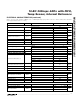
-0.4
-0.3
-0.2
-0.1
0
0.1
0.2
0.3
0.4
0 256 512 768 1024
INTEGRAL NONLINEARITY
vs. OUTPUT CODE
MAX1027/29/31 toc01
OUTPUT CODE
INTEGRAL NONLINEARITY (LSB)
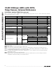
-0.4
-0.3
-0.2
-0.1
0
0.1
0.2
0.3
0.4
0 256 512 768 1024
DIFFERENTIAL NONLINEARITY
vs. OUTPUT CODE
MAX1027/29/31 toc02
OUTPUT CODE
DIFFERENTIAL NONLINEARITY (LSB)
SINAD vs. FREQUENCY
MAX1027/29/31 toc03
FREQUENCY (kHz)
SINAD AMPLITUDE (dB)
100101
10
20
30
40
50
60
70
80
90
100
0
0.1 1000
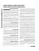
Typical Operating Characteristics
(V
DD
= +3V, V
REF
= +2.5V, f
SCLK
= 4.8MHz, C
LOAD
= 30pF, T
A
= +25°C, unless otherwise noted.)