
User Manual


MAX125/MAX126
2x4-Channel, Simultaneous-Sampling
14-Bit DAS
______________________________________________________________________________________ 13
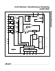
Figure 10. Vector Motor Control
brought to the MAX125/MAX126 at CH4B. The addi-
tional channels can be used to evaluate slower analog
inputs, such as the main DC bus voltage (CH2B), tem-
perature sensors (CH3B), or other analog inputs (AUX,
CH1B).
Power-Supply Bypassing
and Ground Management
For optimum system performance, use printed circuit
boards with separate analog and digital ground
planes. Wire-wrapped boards are not recommended.
Connect the two ground planes together at the low-
impedance power-supply source. Connect DGND and
AGND together at the IC. For the best ground connec-
tion, connect the DGND and AGND pins together and
connect that point to the system analog ground plane
to avoid interference from other digital noise sources. If
DGND is connected to the system digital ground, digi-
tal noise may get through to the ADC’s analog portion.
The AGND pins must be connected directly to a low-
impedance ground plane. Extra impedance between
the pins and the ground plane increases crosstalk and
degrades INL.
Bypass AV
DD
and AV
SS
with 0.1µF ceramic capacitors
to AGND. Mount them with short leads close to the
device. Ferrite beads may also be used to further iso-
late the analog and digital power supplies. Bypass
DV
DD
with a 0.1µF ceramic capacitor to DGND.
MAIN DC
14 BIT ADC +
MICRO-
SEQUENCER
CH1
CH2
CH3
CH4
A
B
A
B TEMP
A
B
A
B AUX
MAIN DC
CURRENT/TORQUE
FEEDBACK
VOLTAGE/POSITION
FEEDBACK
VELOCITY
FEEDBACK
AC
MOTOR
SIMULTANEOUS T/H
MAX125
MAX126
AC
MOTOR
R/E
RESOLVER/
ENCODER
µC
DSP
14
BUFFER
POWER
STAGE
CONTROLLER
EXTERNAL
SETPOINTS