
User Manual


MAX125/MAX126
2x4-Channel, Simultaneous-Sampling
14-Bit DAS
4 _______________________________________________________________________________________
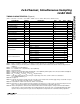
CONDITIONS UNITSMIN TYP MAXSYMBOLPARAMETER
I
OUT
= 1mA V4V
OH
Output High Voltage
I
OUT
= -1.6mA V0.4V
OL
Output Low Voltage
D0–D13 µA±10Three-State Leakage Current
(Note 7) pF10
Three-State Output
Capacitance
V4.75 5 5.25AV
DD
Positive Supply Voltage
V-5.25 -5 -4.75AV
SS
Negative Supply Voltage
V4.75 5 5.25DV
DD
Digital Supply Voltage
mA17 25I(AV
DD
)Positive Supply Current
mA-17 -13I(AV
SS
)Negative Supply Current
mA3 5I(DV
DD
)Digital Supply Current
mA3Shutdown Positive Current
mA-1Shutdown Negative Current
mA3Shutdown Digital Current
(Note 11) LSB±1 ±2PSRR+Positive Supply Rejection
(Note 11) LSB±2PSRR-Negative Supply Rejection
(Note 12) mW165 250Power Dissipation
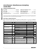
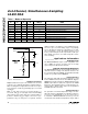
DIGITAL OUTPUTS (D0–D13, INT) (Note 1)
POWER REQUIREMENTS
ELECTRICAL CHARACTERISTICS (continued)
(AV
DD
= +5V ±5%, AV
SS
= -5V ±5%, DV
DD
= +5V ±5%, V
REFIN
= 2.5V, AGND = DGND = 0V, 4.7µF capacitor from REFOUT to
AGND, 0.1µF capacitor from REFIN to AGND, f
CLK
= 16MHz, external clock, 50% duty cycle, T
A
= T
MIN
to T
MAX
, unless otherwise
noted.)