
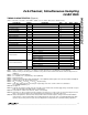
User Manual


Between conversions, the buffer input is connected to
channel 1 of the selected track/hold bank. When a
channel is not selected, switches S1, S2, and S3 are
placed in hold mode to improve channel-to-channel
isolation.
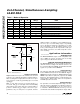
Digital Interface
Input data (A0–A3) and output data (D0–D13) are multi-
plexed on a three-state bidirectional interface. This par-
allel I/O can easily be interfaced with a microprocessor
(µP) or DSP. CS, WR, and RD control the write and read
operations. CS is the standard chip-select signal, which
enables the controller to address the MAX125/MAX126
as an I/O port. When CS is high, it disables the WR and
RD inputs and forces the interface into a high-Z state.
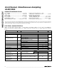
Figure 4 details the interface timing.
Programming Modes
The MAX125/MAX126 have eight conversion modes
plus power-down, which are programmed through a
bidirectional parallel interface. At power-up, the devices
default to the mode
Input Mux A/Single-Channel
Conversion.
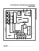
The user can select between two banks
(mux inputs A or mux inputs B) of four simultaneous-
sampled input channels, as illustrated in Figure 2. An
internal microsequencer can be programmed to convert
one, two, three, or four channels of the selected bank
per sample. For a single-channel conversion, CH1 is
digitized, and then INT goes low to indicate completion
of the conversion. For multichannel conversions, INT
goes low after the last channel has been digitized.
To input data into the MAX125/MAX126, pull CS low,
program the bidirectional pins A0–A3 (Table 1), and
pulse WR low. Data is latched into the devices on the
WR or CS rising edge. The ADC is now ready to convert.
Once programmed, the ADCs continue operating in the
same mode until they are reprogrammed or until power
is removed. Figure 5 shows an example of program-
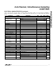
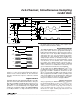
ming a four-channel conversion using Input Mux A.
Starting a Conversion
After programming the MAX125/MAX126 as outlined in
the
Programming Modes
section, pulse CONVST low to
initiate a conversion sequence. The analog inputs are
sampled at the CONVST rising edge. Do not start a
new conversion while the conversion is in progress.
Monitor the INT output. A falling edge indicates the end
of a conversion sequence.
MAX125/MAX126
2x4-Channel, Simultaneous-Sampling
14-Bit DAS
_______________________________________________________________________________________ 9
CH1 CH2 CH3 CH4
t
ACQ
t
CONV
t
AH
t
AS
t
WR
t
CSD
t
CWH
t
DH
t
DA
t
RD
t
CRS
t
CRH
t
RD
t
ID
t
CWS
CONVST
INT
CS
WR
DATA
t
CW
DATA IN
RD
Figure 4. Timing Diagram
Figure 5. Programming a Four-Channel Conversion, Input Mux A
A0
(LSB)
WR
CS
A1
A2
A3