
Instruction Manual

10 _____________________________________________________________________________________
MAX14805/MAX14806
16-Channel (Two Banks of 8-Channel),
High-Voltage Analog Switches
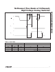
Detailed Description
The MAX14805/MAX14806 provide high-voltage switch-
ing on 16 channels for ultrasonic imaging. Both devices
are ideal for the following applications: bank selection in
biplane or triplane ultrasound probes and relays replace-
ment in medical ultrasound systems. The devices utilize
200V process technology to provide 16 high-voltage,
low-charge injection SPST switches, controlled by a
digital interface.
The MAX14805/MAX14806’s output switches are con-
figured as two sets of eight SPST analog switches. The
switches are controlled by two input logic controls, DIN1
and DIN2 (respectively for switch 0 to 7 and switch 8
to 15). The MAX14806 features integrated 40kI bleed
resistors on each switch terminal that help to reduce
voltage buildup in capacitive loads such as piezoelectric
elements.
The MAX14805/MAX14806 operate with a wide range of
high-voltage supplies, including V
PP
/V
NN
= +100V/-100V,
+200V/0V and +40V/-160V. The digital interface oper-
ates from a separate V
DD
supply from +2.7V to +5.5V.
Digital inputs DIN1, DIN2, and LE operate on the V
DD
supply voltage.
The MAX14805CCM+ is a drop-in replacement for the
Supertex HV2631. The MAX14806CCM+ is a drop-in
replacement for the Supertex HV2731.
Analog Switch
The MAX14805/MAX14806 allow a peak-to-peak analog
signal range from V
NN
to (V
PP
- 10V). During power-up
and power-down, all analog switch inputs (SW_) must be
unconnected or satisfy V
NN
P V
SW_
P V
PP
.
High-Voltage Supplies
The MAX14805/MAX14806 allow a wide range of high-
voltage supplies. The devices operate with V
NN
from
-160V to 0V and V
PP
from +40V to (V
NN
+ 220V). When
V
NN
is connected to GND (single-supply applications),
the devices operate with V
PP
up to +200V. The V
PP
and
V
NN
high-voltage supplies are not required to be sym-
metrical, but the voltage difference (V
PP
- V
NN
) must not
exceed 230V.
Bleed Resistors (MAX14806)
The MAX14806 features integrated 40kI bleed resis-
tors to discharge capacitive loads such as piezoelectric
transducers. Each analog switch terminal is connected
to GND with a bleed resistor.
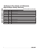
Data Input (DIN1/DIN2)
DIN1/DIN2 control the on/off state of the analog switches.
DIN1 controls SW0–SW7 and DIN2 controls SW8–SW15
(see Table 1 and Figure 2). DIN1 and DIN2 operate on
the V
DD
supply voltage.
Latch Enable (LE)
Drive LE logic-low to latch DIN1/DIN2 data input (see
Figure 2). Drive LE logic-high to hold data. The LE input
operates on the V
DD
supply voltage.
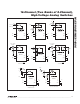
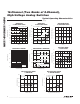
Applications Information
For medical ultrasound applications, see Figures 3 and 4.
Supply Sequencing and Bypassing
The MAX14805/MAX14806 do not require special
sequencing of the V
DD
, V
PP
, and V
NN
supply voltages;
however, analog switch inputs must be unconnected or
satisfy V
NN
P V
SW_
P V
PP
during power-up and power-
down. Bypass V
DD
, V
PP
, and V
NN
to GND with a 0.1FF
ceramic capacitor as close as possible to the device.