
Instruction Manual

4 ______________________________________________________________________________________
MAX14805/MAX14806
16-Channel (Two Banks of 8-Channel),
High-Voltage Analog Switches
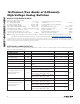
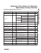
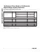
ELECTRICAL CHARACTERISTICS (continued)
(V
DD
= +2.7V to +5.5V, V
PP
= +40V to (V
NN
+ 200V), V
NN
= -40V to -160V, T
A
= T
MIN
to T
MAX
, unless otherwise noted. Typical
values are at T
A
= +25NC.) (Note 2)
Note 2: All devices are 100% tested at T
A
= +85NC. Limits over the operating temperature range are guaranteed by design and
characterization.
Note 3: The analog signal input V
SW_
must satisfy V
NN
P V
SW_
P V
PP
or remain unconnected during power-up.
Note 4: Guaranteed by characterization; not production tested.
PARAMETER SYMBOL CONDITIONS MIN TYP MAX UNITS
Charge Injection Q
V
PP
= +40V, V
NN
= -160V, V
SW_
= 0V
(Figure 1)
650
pC
V
PP
= +100V, V
NN
= -100V, V
SW_
= 0V
(Figure 1)
450
V
PP
= +160V, V
NN
= -40V, V
SW_
= 0V
(Figure 1)
250
LOGIC LEVELS (DIN1, DIN2, LE)
Logic-Input Low Voltage V
IL
0.75 V
Logic-Input High Voltage V
IH
V
DD
-
0.75
V
Logic-Input Capacitance C
IN
10 pF
Logic-Input Leakage Current I
IN
-1 +1
FA
LOGIC TIMING (See Timing Diagram, Figure 2)
Setup Time t
SD
30 ns
Hold Time t
HOLD
30 ns
Time Width of LE
t
WLE
30 ns