
Manual
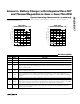

MAX1507
Linear Li+Battery Charger with Integrated Pass FET
and Thermal Regulation in 3mm x 3mm Thin DFN
_______________________________________________________________________________________ 9
Application Circuits
Stand-Alone Li+ Charger
The MAX1507 provides a complete Li+ charging solu-
tion. The Typical Application Circuit on the front page
shows the MAX1507 as a stand-alone Li+ battery
charger. The 2.8kΩ resistor connected to ISET sets a
charging current of 520mA. The LED indicates when
either fast-charge or precharge qualification has
begun. When the battery is full, the LED turns off.
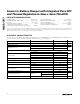
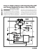
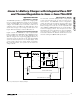
Microprocessor-Interfaced Charger
Figure 3 shows the MAX1507 as a µP-cooperated Li+
battery charger. The MAX1507 starts charging the bat-
tery when EN is low. The µP can drive EN high to dis-
able the charger. Use a logic-biased NPN transistor as
an inverter circuit to generate an AC_ON signal for the
system to detect the presence of an input supply. CHG
can be used to detect the charge status of a battery.
By monitoring V
ISET
, the system can measure the
charge current.
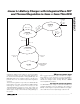
USB-Powered Li+ Charger
The universal serial bus (USB) provides a high-speed
serial communication port as well as power for the
remote device. The MAX1507 can be configured to
charge its battery at the highest current possible from
the host port. Figure 4 shows the MAX1507 as a USB
battery charger. To make the circuit compatible with
either 100mA or 500mA USB ports, the circuit initializes
at 95mA charging current. The microprocessor then
interrogates the host to determine its current capability.
If the host port is capable, the charging current is
increased to 435mA. The 435mA current was chosen to
avoid exceeding the 500mA USB specification.
MAX1507
1µF
2.8kΩ
IN
CHG
1µF
4.2V Li+
BATT
EN
GND
SYSTEM
TEMP
VL
ISET
AC/DC
ADAPTER
VI/O
ROHM
DTC114EM
VI/O
AC_ON
CHARGE-CURRENT MONITOR
LOW: CHARGE, HIGH: FULL OR OFF
0.47µF
Figure 3. µP Interfaced Li+ Battery Charger