
Manual

MAX1508
Li+ Linear Battery Charger with Integrated Pass FET,
Thermal Regulation, and
ACOK
in 3mm x 3mm TDFN
_______________________________________________________________________________________ 5
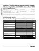
Pin Description
PIN NAME FUNCTION
1 VL Internally Generated Logic Supply for Chip. Bypass VL to GND with a 0.47µF capacitor.
2 IN Input Supply Voltage. Bypass IN to GND with a 1µF capacitor to improve line noise and transient rejection.
3 GND Ground. Connect GND and exposed pad to a large copper trace for maximum power dissipation.
4 ISET
Charge-Current Program and Fast-Charge Current Monitor. Output current from ISET is 0.958mA per amp of
battery charging current. The charging current is set by connecting a resistor from ISET to GND. Fast-charge
current = 1461V / R
ISET
Ω.
5 EN
Logic-Level Enable Input. Drive EN high to disable charger. Pull EN low or float for normal operation. EN has
an internal 200kΩ pulldown resistor.
6 ACOK
Input Power-Detection Output. The open-drain ACOK output asserts low when +4.25V
< V
IN
< +7V and V
IN
-
V
BATT
> 40mV. ACOK requires an external 100kΩ pullup resistor. ACOK is high impedance in shutdown.
7 BATT Li+ Battery Connection. Bypass BATT to GND with a capacitor of at least 1µF per ampere of charge current.
8 CHG
Charging Indicator, Open-Drain Output. CHG goes low (and can turn on an LED) when charging begins.
CHG is high impedance when the battery current drops below 10% of the fast-charging current, or when EN
is high. Connect a pullup resistor to the µP’s I/O voltage when interfacing with a µP logic input.
— PAD
Exposed Pad. Connect exposed pad to a large copper trace for maximum power dissipation. The pad is
internally connected to GND.
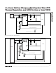
Detailed Description
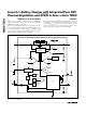
The MAX1508 charger uses voltage, current, and ther-
mal-control loops to charge a single Li+ cell and to pro-
tect the battery (Figure 1). When a Li+ battery with a cell
voltage below 2.5V is inserted, the MAX1508 charger
enters the prequalification stage where it precharges that
cell with 10% of the user-programmed fast-charge cur-
rent. The CHG indicator output is driven low (Figure 2) to
indicate entry into the prequalification state. Once the
cell has passed 2.5V, the charger soft-starts before it
enters the fast-charge stage. The fast-charge current
level is programmed through a resistor from ISET to
ground. As the battery voltage approaches 4.2V, the
charging current is reduced. If the battery current drops
to less than 10% of the fast-charging current, the CHG
indicator goes high impedance, signaling the battery is
fully charged. At this point the MAX1508 enters a con-
stant voltage-regulation mode to maintain the battery at
full charge. If, at any point while charging the battery, the
die temperature approaches +100°C, the MAX1508
reduces the charging current so the die temperature
does not exceed the temperature-regulation set point.
The thermal-regulation loop limits the MAX1508 die
temperature to +100°C by reducing the charge current
as necessary (see the Thermal Regulation section).
This feature not only protects the MAX1508 from over-
heating, but also allows higher charge current without
risking damage to the system.
EN
Charger Enable Input
EN is a logic input (active low) to enable the charger.
Drive EN low, leave floating, or connect to GND to
enable the charger control circuitry. Drive EN high to
disable the charger control circuitry. EN has a 200kΩ
internal pulldown resistance.
ACOK
Output
Active-Low Output. The open-drain ACOK output
asserts low when +4.25V < V
IN
< +7V and V
IN
- V
BATT
> 40mV. ACOK requires an external 100kΩ pullup
resistor to the system’s logic I/O voltage. ACOK is high
impedance in shutdown.
VL Internal Voltage Regulator
The MAX1508 linear charger contains an internal linear
regulator available on the VL output pin. VL requires a
0.47µF ceramic bypass capacitor to GND. VL is regulat-
ed to 3.3V whenever the input voltage is above 3.5V.