
Owner manual


MAX1538
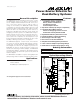
Power-Source Selector for
Dual-Battery Systems
10 ______________________________________________________________________________________
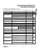
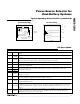
PIN NAME FUNCTION
14
ADPBLK
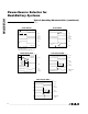
Gate Drive for the Adapter-Blocking P-Channel MOSFET. Connect ADPBLK to the gate of P3 (Figure 1). P3
enables and disables the battery discharge path. ADPBLK is driven relative to EXTLD. ADPBLK and
DISBAT are driven with the same control signal.
15, 21 N.C. Not Internally Connected
16
EXTLD
External Load. EXTLD is the supply rail for REVBLK and ADPBLK.
17
CHGIN
Charger Node Input. CHGIN is the supply rail for DISBAT, CHGA, and CHGB.
18
DISBAT
Gate Drive for the Battery-Discharge P-Channel MOSFET. Connect DISBAT to the gate of P4 (Figure 2). P4
disconnects the battery from the system load when charging from a step-up converter. Exclude P4 and
leave DISBAT disconnected if using a step-down charger. DISBAT is driven relative to CHGIN. DISBAT and
ADPBLK are driven by the same control signal.
19 CHGA
Gate Drive for the Charge Battery A P-Channel MOSFET. Connect CHGA to the gate of P6 (Figure 1). P6
enables and disables the charge path into battery A. CHGA is driven relative to CHGIN. CHGA and DISA
are driven by the same control signal.
20 CHGB
Gate Drive for the Charge Battery B P-Channel MOSFET. Connect CHGB to the gate of P7 (Figure 1). P7
enables and disables the charge path into battery B. CHGB is driven relative to CHGIN. CHGB and DISB
are driven by the same control signal.
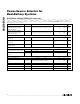
22 BATB
Battery B Voltage Input. Battery undervoltage and absence is determined by measuring BATB. BATB is the
supply rail for DISB.
23 DISB
Gate Drive for the Discharge from Battery B P-Channel MOSFET. Connect DISB to the gate of P8 (Figure 1).
P8 enables and disables the discharge path from battery B. DISB is driven relative to BATB. DISB and
CHGB are driven by the same control signal.
24 DISA
Gate Drive for the Discharge from Battery A P-Channel MOSFET. Connect DISA to the gate of P5 (Figure 1).
P5 enables and disables the discharge path from battery A. DISA is driven relative to BATA. DISA and
CHGA are driven by the same control signal.
25 BATA
Battery A Voltage Input. Battery undervoltage and absence is determined by measuring BATA. BATA is the
supply rail for DISA.
26
BATSUP
BATSUP powers the MAX1538. Diode OR BATA and BATB to BATSUP externally. ADPIN is diode
connected to BATSUP internally. Bypass with a 0.1µF capacitor from BATSUP to GND.
27 GND Ground
28 V
DD
Linear-Regulator Output. Bypass with a 1µF capacitor from V
DD
to GND.
Pin Description (continued)