
Owner manual
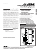


MAX1538
Power-Source Selector for
Dual-Battery Systems
2 _______________________________________________________________________________________
ABSOLUTE MAXIMUM RATINGS
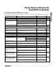
ELECTRICAL CHARACTERISTICS
(V
BATA
= V
BATB
= V
CHGIN
= 16.8V, C
VDD
= 1µF, V
MINVA
= V
MINVB
= 0.93V, V
EXTLD
= V
ADPIN
= 28V, V
CHRG
= V
BATSEL
= V
RELRN
= 0,
C
ADPPWR
= C
REVBLK
= C
ADPBLK
= C
DISBAT
= C
DISA
= C
DISB
= C
CHGA
= C
CHGB
= 4.7nF, T
A
= 0°C to +85°C, unless otherwise noted.
Typical values are at T
A
= +25°C.)
Stresses beyond those listed under “Absolute Maximum Ratings” may cause permanent damage to the device. These are stress ratings only, and functional
operation of the device at these or any other conditions beyond those indicated in the operational sections of the specifications is not implied. Exposure to
absolute maximum rating conditions for extended periods may affect device reliability.
V
EXTLD
, V
BATSUP
, V
ADPIN
, V
BATA
, V
BATB
,
V
CHGIN
to GND .................................................-0.3V to +30V
V
ADPPWR
to GND...................................-0.3V to (V
ADPIN
+ 0.3V)
V
REVBLK
, V
ADPBLK
to GND ...................-0.3V to (V
EXTLD
+ 0.3V)
V
CHGA
, V
CHGB,
V
DISBAT
to GND ..........-0.3V to (V
CHGIN
+ 0.3V)
V
DISA
to GND..........................................-0.3V to (V
BATA
+ 0.3V)
V
DISB
to GND..........................................-0.3V to (V
BATB
+ 0.3V)
V
DD
, V
CHRG
, V
BATSEL
, V
RELRN
, V
OUT0
, V
OUT1
, V
OUT2
,
V
MINVA
, V
MINVB
, V
AIRDET
, V
ACDET
to GND..........-0.3V to +6V
Continuous Power Dissipation (T
A
= +70°C)
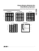
28-Pin Thin QFN 5mm x 5mm
(derate 20.8mW/°C above +70°C)..........................1666.7mW
Operating Temperature Range
MAX1538ETI ....................................................-40°C to +85°C
Junction Temperature......................................................+150°C
Storage Temperature Range .............................-65°C to +150°C
Lead Temperature (soldering, 10s) .................................+300°C
PARAMETER CONDITIONS
MIN
TYP
MAX
UNITS
ADPIN, EXTLD Supply Voltage
Range
4.75 28.00
V
CHGIN, BATA, BATB and
BATSUP Supply Voltage Range
4.75 19.00
V
V
ADPIN
= highest,
V
ADPPWR
= high
21 50
V
ADPIN
= highest,
V
ADPPWR
= low
23 54
V
BATA
= highest,
V
DISA
= high
21 42
V
BATA
= highest, V
DISA
= low
24 50
V
BATB
= highest,
V
DISB
= high
21 42
V
BATB
= highest, V
DISB
= low
24 50
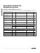
ADPIN, BATA, BATB, BATSUP
Quiescent Current (Current from
the Highest Voltage Supply)
V
BATA
= 4.75V to 19V,
V
BATB
= 4.75V to 19V,
V
BATSUP
= 4.75V to 19V,
V
ADPIN
= 4.75V to 28V,
no external load at V
DD
V
BATSUP
= highest 18 40
µA
V
ADPPWR
= high
0.01
0.5
ADPIN Quiescent Current (ADPIN
Current When Not the Highest
Voltage)
V
ADPIN
= 4.75V to 18V,
no external load at V
DD
V
ADPPWR
= low 2.6 6
µA
V
DISA
= high 3.9 6.0
BATA Quiescent Current (BATA
Current When Not the Highest
Voltage)
V
BATA
= 4.75V to 19V,
no external load at V
DD
V
DISA
= low 7.0 12
µA
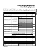
V
DISB
= high 3.9 6.0
BATB Quiescent Current (BATB
Current When Not the Highest
Voltage)
V
BATB
= 4.75V to 19V,
no external load at V
DD
V
DISB
= low 7.0 12
µA
Adapter selected (REVBLK or ADPBLK pins low) 3.0 6.1
EXTLD Quiescent Current
Adapter not selected (REVBLK and ADPBLK pins high)
0.02
1.0
µA
AC or ai r l i ne state ( C H G A, C H GB, and D IS BAT p i ns hi g h)
0.03
1.5
Charge state (CHGA or CHGB pin low, DISBAT pin high)
3.1 6.2
CHGIN Quiescent Current
Discharge or relearn state (CHGA or CHGB pin low,
DISBAT pin low)
6.1
12.1
µA