
User Manual


MAX1578/MAX1579
Complete Bias and White LED Power Supplies
for Small TFT Displays
10 ______________________________________________________________________________________
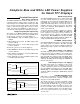
Soft-Start
The LED boost converter utilizes a soft-start function to
eliminate inrush current during startup. Once the boost
converter is enabled, LX begins switching at the mini-
mum duty cycle until C
COMP
is charged to 1.25V. Once
this occurs, the duty cycle increases to further charge
the output until V
CS
reaches 20% of V
CTRL
. The soft-
start time is adjustable using the capacitor from COMP
to GND. Calculate the required COMP capacitor as:
where t
SS
is the desired soft-start time in seconds.
Overvoltage Protection
The output of the LED boost converter is protected from
overvoltage conditions by internal overvoltage circuitry.
If V
OUT
exceeds 34V, the LX switching terminates.
Once V
OUT
falls below 32V, LX switches normally and
soft-start is re-initiated.
Ambient Temperature Derating Function
(MAX1579)
The MAX1579 limits the maximum LED current depend-
ing on the die temperature. V
CS
is limited to 340mV up
to +42°C. Once the temperature reaches +42°C, the
maximum V
CS
declines by 6mV/°C until the minimum
40mV threshold is reached at +100°C. Due to the pack-
age’s exposed paddle, the die temperature is always
very close to the PC board temperature.
The temperature derating function allows the LED cur-
rent to be safely set higher at normal operating temper-
atures, thereby allowing either a brighter display or
fewer LEDs to be used for normal display brightness.
Shutdown
The MAX1578/MAX1579 include a low-quiescent-current
shutdown mode. To enter shutdown, drive CTRL below
0.1V for longer than 10.5ms and drive ONBIAS low. The
quiescent current is reduced to less than 1µA when the
boost converter and charge pumps are disabled.
To disable the LED boost converter, drive CTRL below
0.1V for longer than 10.5ms. During shutdown, the
internal boost switch from LX to PGND is high imped-
ance; however, a DC path exists from IN to OUT
through the external inductor and Schottky diode. Drive
CTRL with an analog voltage between 0.24V and 1.65V
or a 200Hz to 200kHz digital PWM dimming signal for
normal operation. The quiescent current is reduced to
870µA when the boost converter is shut down and the
charge pumps are enabled.
Drive ONBIAS low to shut down the internal POS and
NEG charge pumps and disable the MAIN LDO output.
On-chip pulldown resistors discharge these outputs
during shutdown. Drive ONBIAS high for normal opera-
tion. V
DD
is connected to IN when ONBIAS is low. The
quiescent current is reduced to 430µA when the charge
pumps are shut down and the boost converter is
enabled.
Applications Information
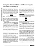
Adjusting LED Current
Set the maximum LED current using a resistor from CS
to GND. Calculate the resistance as follows:
where I
LED
is the desired maximum current through the
LEDs in Amps when V
CTRL
is 1.65V.
LED Dimming Control Using a DAC
V
CTRL
controls the LED drive current. The voltage at CS
regulates to 20% of V
CTRL
to control the current
through the LEDs and, therefore, the brightness. Drive
CTRL using a DAC with an output voltage between
0.24V and 1.65V to control the brightness of the LEDs.
Increasing V
CTRL
beyond 1.65V results in no further
brightness increase. Hold CTRL below 100mV for
longer than 10.5ms to shut down the boost converter.
LED Dimming Using Direct PWM into CTRL
Another useful technique for LED dimming control is the
application of a logic-level PWM signal applied directly
to CTRL. LED current may be varied from zero to full
scale. The frequency range of the PWM signal is from
200Hz to 200kHz, while 0% duty cycle corresponds to
zero current and 100% duty cycle corresponds to full
current. The error amplifier and compensation capaci-
tor form a lowpass filter so PWM dimming results in DC
current to the LEDs without the need for any additional
RC filters. See the Typical Operating Characteristics.
Input/Output Ripple
For LED drivers, input and output ripple may be impor-
tant. Input ripple depends on the source supply’s output
impedance. Adding a lowpass filter to the input further
reduces input ripple. Alternately, increasing C
IN
to 10µF
cuts input ripple in half. Likewise, an output filter or high-
er output capacitance value reduces output ripple.
R
mV
I
for the MAX
R
mV
I
for the MAX
CS
LED
CS
LED
=
=
330
1578
340
1579
C
At
V
COMP
SS
=
×12
125
µ
.