
Manual

MAX1684/MAX1685
Low-Noise, 14V Input, 1A, PWM
Step-Down Converters
8 _______________________________________________________________________________________
_______________Detailed Description
The MAX1684/MAX1685 step-down, PWM DC-DC con-
verters provide an adjustable output from 1.25V to the
input voltage. They accept inputs from 2.7V to 14V and
deliver up to 1.6A. An internal MOSFET and synchro-
nous rectifier reduce PC board area while maintaining
high efficiency. Operation with up to 100% duty cycle
minimizes dropout voltage. Fixed-frequency PWM oper-
ation reduces interference in sensitive communications
and data-acquisition applications. A SYNC input allows
synchronization to an external clock. The
MAX1684/MAX1685 can operate in five modes. Setting
the devices to operate in the appropriate mode for the
intended application (Table 1) achieves highest effi-
ciency.
PWM Control
The MAX1684/MAX1685 use an oscillator-triggered min-
imum/maximum on-time current-mode control scheme
(Figure 2). The minimum on-time is typically 220ns
unless the regulator is in dropout. The maximum on-time
is 2 / f
OSC
, allowing operation to 100% duty cycle.
Current-mode feedback provides cycle-by-cycle current
limiting for superior load- and line-transient response.
At each falling edge of the internal oscillator, the inter-
nal P-channel MOSFET (main switch) turns on. This
allows current to ramp up through the inductor to the
load and stores energy in a magnetic field. The switch
remains on until either the current-limit comparator
trips, the maximum on-time expires, or the PWM com-
parator signals that the output is in regulation. When
the switch turns off during the second half of each
cycle, the inductor’s magnetic field collapses, releasing
the stored energy and forcing current through the out-
put diode to the output filter capacitor and load. The
output filter capacitor stores charge when the inductor
current is high and releases it when the inductor cur-
rent is low, smoothing the voltage across the load.
During normal operation, the MAX1684/MAX1685 regu-
late the output voltage by switching at a constant fre-
quency and modulating the power transferred to the
load on each cycle using the PWM comparator. A multi-
input comparator sums three weighted differential sig-
nals (the output voltage with respect to the reference,
the main switch current sense, and the slope-compen-
sation ramp) and changes states when a threshold is
reached. It modulates output power by adjusting the
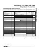
MAX1685
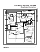
LX
13, 14
L
10µH*
MBRS
130LT3
16
5
12
7
IN
CVH
AIN
PGND
AGND
OUTPUT
3.3V AT 1A
*SUMIDA
CD54-100;
USE 22µH FOR MAX1684
INPUT
14V MAX
BOOT
FB
SHDN
CVL
4
15
2
3
1
11
1µF
0.1µF
0.1µF
22µF
C
OUT
100µF
0.1µF 0.1µF
0.01µF
ON/OFF
9
STBY
SYNC/PWM
ILIM/SS CC
6810
REF
(OPTIONAL)
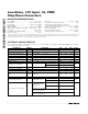
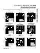
Figure 1. Standard Application Circuit
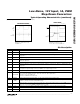
Table 1. Operating Modes
Fixed-frequency PWMHPWM
MODE FUNCTIONSYNC/PWM
H
STBY
H
SHDN
1.6
TYPICAL
OUTPUT
CAPABILITY (A)
H H 1.6Fixed-input clock-frequency PWMClockedSync PWM
H H 1.6
PFM at light loads (<150mA); fixed-
frequency PWM at heavy loads (>150mA)
LNormal
L H 160mLow-power or standby modeXLow Power
X L 0Circuit disabledXShutdown