
User guide
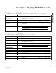
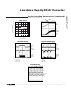

Typical Operating Characteristics
(Circuit of Figure 1, V
IN
= 3.3V, f
OSC
= 640kHz, T
A
= +25°C, unless otherwise noted.)
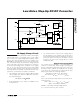
MAX17067
Low-Noise Step-Up DC-DC Converter
4 _______________________________________________________________________________________
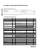
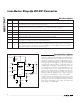
ELECTRICAL CHARACTERISTICS (continued)
(V
IN
= SHDN = 3V, FREQ = 3V, T
A
= -40°C to +85°C, unless otherwise noted.) (Note 1)
PARAMETER SYMBOL CONDITIONS MIN TYP MAX UNITS
n-CHANNEL SWITCH
Current Limit I
LIM
V
FB
= 1V, duty cycle = 68% (Note 4) 1.8 3.4 A
On-Resistance R
ON
V
IN
= 3V 275
Current-Sense Transresistance R
CS
0.19 0.40 V/A
SOFT-START
Reset Switch Resistance 100
Charge Current V
SS
= 1.2V 2.5 6.5 μA
CONTROL INPUTS
Input Low Voltage V
IL
SHDN, FREQ, V
IN
= 2.6V to 4.0V
0.3 x
V
IN
V
Input High Voltage V
IH
SHDN, FREQ, V
IN
= 2.6V to 4.0V
0.7 x
V
IN
V
Note 1: Limit on IN absolute maximum ratings is for operation without the use of an external resistor for the internal clamp circuit.
See the
IN Supply Clamp Circuit
section for IN voltage limits during clamping circuit operation.
Note 2: Limits are 100% production tested at T
A
= +25°C. Maximum and minimum limits over temperature are guaranteed by design
and characterization.
Note 3: See the
IN Supply Clamp Circuit
section to properly size the external resistor.
Note 4: Current limit varies with duty-cycle slope compensation. See the
Output-Current Capability
section.
MAX17067 toc01
50
1 100010010
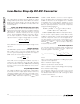
EFFICIENCY vs. L0AD CURRENT
(V
IN
= 3.3V, V
OUT
= 9V)
70
90
80
100
60
LOAD CURRENT (mA)
EFFICIENCY (%)
f
OSC
= 1.2MHz
L
= 3.3μH
f
OSC
= 640kHz
L
= 4.7μH
-0.5
1 100010010
STEP-UP CONVERTER
LOAD REGULATION
0
1.0
0.5
MAX17067 toc02
LOAD CURRENT (mA)
REGULATION (%)
L
= 3.3μH
INPUT VOLTAGE (V)
500
2.5 5.54.53.5 5.04.03.0
SWITCHING FREQUENCY
vs. INPUT VOLTAGE
800
600
1200
1000
1400
900
700
1300
1100
MAX17067 toc03
SWITCHING FREQUENCY (kHz)
FREQ = IN
FREQ = GND