
User guide
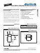
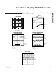

MAX17067MAX17067
Low-Noise Step-Up DC-DC Converter
8 _______________________________________________________________________________________
Soft-Start
The MAX17067 can be programmed for soft-start upon
power-up with an external capacitor. When the shut-
down pin is taken high, the soft-start capacitor (C
SS
) is
immediately charged to 0.5V. Then the capacitor is
charged at a constant current of 4.5μA (typ). During
this time, the SS voltage directly controls the peak
inductor current, allowing 0A at V
SS
= 0.5V to the full
current limit at V
SS
= 1.5V. The maximum load current
is available after the soft-start cycle is completed.
When the shutdown pin is taken low, the soft-start
capacitor is discharged to ground.
Frequency Selection
The MAX17067’s frequency can be user selected to oper-
ate at either 640kHz or 1.2MHz. Connect FREQ to GND
for 640kHz operation. For a 1.2MHz switching frequen-
cy, connect FREQ to IN. This allows the use of small,
minimum-height external components while maintaining
low output noise. FREQ has an internal pulldown, allow-
ing the user the option of leaving FREQ unconnected
for 640kHz operation.
Shutdown
The MAX17067 is shut down to reduce the supply cur-
rent to 30μA when SHDN is low. In this mode, the inter-
nal reference, error amplifier, comparators, and biasing
circuitry turn off while the n-channel MOSFET is turned
off. The boost converter’s output is connected to IN by
the external inductor and catch diode.
Thermal-Overload Protection
Thermal-overload protection prevents excessive power
dissipation from overheating the MAX17067. When the
junction temperature exceeds T
J
= +160°C, a thermal
sensor immediately activates the fault protection, which
shuts down the MAX17067, allowing the device to cool
down. Once the device cools down by approximately
20°C, it returns to normal operation.
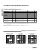
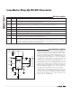
Applications Information
Boost DC-DC converters using the MAX17067 can be
designed by performing simple calculations for a first
iteration. All designs should be prototyped and tested
prior to production. Table 1 provides a list of compo-
nents for a range of standard applications. Table 2 lists
component suppliers.
External component value choice is primarily dictated
by the output voltage and the maximum load current,
as well as maximum and minimum input voltages.
Begin by selecting an inductor value. Once L is known,
choose the diode and capacitors.
Inductor Selection
The minimum inductance value, peak current rating, and
series resistance are factors to consider when selecting
the inductor. These factors influence the converter’s effi-
ciency, maximum output load capability, transient-
response time, and output voltage ripple. Physical size
and cost are also important factors to be considered.
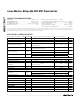
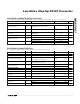
Table 2. Component Suppliers
847-639-6400
561-241-7876
847-956-0666
PHONE
847-639-1469Coilcraft
561-241-9339Coiltronics
847-956-0702Sumida USA
FAXSUPPLIER
803-946-0690
408-986-0424
619-661-6835
847-297-0070
803-626-3123AVX
408-986-1442KEMET
619-661-1055SANYO
847-699-1194TOKO
408-573-4150 408-573-4159Taiyo Yuden
Inductors
Capacitors
PHONE FAXSUPPLIER
516-435-1110
310-322-3331
516-543-7100
602-303-5454
847-843-7500
516-864-7630Zetex
847-843-2798Nihon
516-435-1824
Central
Semiconductor
310-322-3332
International
Rectifier
602-994-6430Motorola
Diodes
Table 1. Component Selection
V
IN
(V) V
OUT
(V) f
OSC
(Hz) L (μH) C
OUT
(μF) R
COMP
(k ) C
COMP
(pF)
C
COMP2
(pF)
I
OUT(MAX)
(mA)
3.3 9 1.2M 3.3 10 121 620 10 250
3.3 9 640k 4.7 10 82 1000 10 250