
User guide

MAX17067
Low-Noise Step-Up DC-DC Converter
_______________________________________________________________________________________ 9
The maximum output current, input voltage, output volt-
age, and switching frequency determine the inductor
value. Very high inductance values minimize the cur-
rent ripple and therefore reduce the peak current,
which decreases core losses in the inductor and I
2
R
losses in the entire power path. However, large induc-
tor values also require more energy storage and more
turns of wire, which increase physical size and can
increase I
2
R losses in the inductor. Low inductance val-
ues decrease the physical size but increase the current
ripple and peak current. Finding the best inductor
involves choosing the best compromise between circuit
efficiency, inductor size, and cost.
The equations used here include a constant LIR, which
is the ratio of the inductor peak-to-peak ripple current to
the average DC inductor current at the full load current.
The best trade-off between inductor size and circuit
efficiency for step-up regulators generally has an LIR
between 0.3 and 0.5. However, depending on the AC
characteristics of the inductor core material and the
ratio of inductor resistance to other power path resis-
tances, the best LIR can shift up or down. If the induc-
tor resistance is relatively high, more ripple can be
accepted to reduce the number of turns required and
increase the wire diameter. If the inductor resistance is
relatively low, increasing inductance to lower the peak
current can decrease losses throughout the power
path. If extremely thin high-resistance inductors are
used, as is common for LCD-panel applications, the
best LIR can increase to between 0.5 and 1.0.
Once a physical inductor is chosen, higher and lower
values of the inductor should be evaluated for efficiency
improvements in typical operating regions.
Calculate the approximate inductor value using the typ-
ical input voltage (V
IN
), the maximum output current
(I
MAIN(MAX)
), the expected efficiency (η
TYP
) taken from
an appropriate curve in the
Typical Operating
Characteristics
, and an estimate of LIR based on the
above discussion:
Choose an available inductor value from an appropriate
inductor family. Calculate the maximum DC input cur-
rent at the minimum input voltage V
IN(MIN)
using con-
servation of energy and the expected efficiency at that
operating point (η
MIN
) taken from an appropriate curve
in the
Typical Operating Characteristics
:
Calculate the ripple current at that operating point and
the peak current required for the inductor:
The inductor’s saturation current rating and the
MAX17067s’ LX current limit (I
LIM
) should exceed I
PEAK
and the inductor’s DC current rating should exceed
I
IN(DC,MAX)
. For good efficiency, choose an inductor with
less than 0.1Ω series resistance.
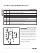
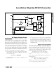
Considering the application circuit in
Figure 4, the maxi-
mum load current (I
MAIN(MAX)
) is 250mA with a 9V output
and a typical input voltage of 3.3V. Choosing an LIR of 0.7
and estimating efficiency of 85% at this operating point:
Using the application’s minimum input voltage (3V) and
estimating efficiency of 80% at that operating point:
The ripple current and the peak current are:
IA
A
A
PEAK
=+≈094
051
2
119.
.
.
I
VVV
HV MHz
A
RIPPLE
=
×−
××
≈
393
33 9 12
051
()
..
.
μ
I
AV
V
A
IN DC MAX(, )
.
.
.=
×
×
≈
025 9
308
094
L
V
V
VV
AMHz
=
⎛
⎝
⎜
⎞
⎠
⎟
−
×
⎛
⎝
⎜
⎞
⎠
⎟
33
9
933
025 12
08
2
..
..
. 55
07
33
.
.
⎛
⎝
⎜
⎞
⎠
⎟
≈μH
II
I
PEAK IN DC MAX
RIPPLE
=+
(, )
2
I
VVV
LV f
RIPPLE
IN MIN MAIN IN MIN
MAIN OSC
=
×−
××
() ()
()
I
IV
V
IN DC MAX
MAIN MAX MAIN
IN MIN MIN
(, )
()
()
=
×
×η
L
V
V
VV
I f LIR
IN
MAIN
MAIN IN
MAIN MAX OSC
TYP
=
⎛
⎝
⎜
⎞
⎠
⎟
−
×
⎛
⎝
⎜
⎞
⎠
⎟
⎛
⎝
⎜
⎞
⎠
⎟
2
()
η