
User Manual


MAX1832–MAX1835
High-Efficiency Step-Up Converters with
Reverse Battery Protection in SOT23-6
6 _______________________________________________________________________________________
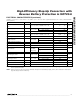
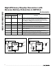
10µH
GND
RST
+1.5V TO +3.3V
OUT
OUTPUT
+3.3V
POWER-ON
RESET
BATT
BATTERY
SHDN
LX
MAX1833
MAX1835
100kΩ
10µF
R4
220kΩ
R3
1MΩ
C1
10nF
10µF
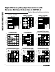
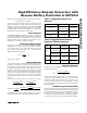
10µH
GND
FB
+1.5V TO +5.0V
OUT
OUTPUT
+5.0V
BATT
BATTERY
SHDN
LX
MAX1832
MAX1834
R2
309kΩ
R1
100kΩ
R3
1MΩ
R4
220kΩ
C1
10nF
10µF
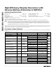
Pin Description
PIN
MAX1832
MAX1834
MAX1833
MAX1835
NAME FUNCTION
11
SHDN
S hutd ow n. A hi g h l og i c l evel tur ns on the d evi ce. W hen SHD N i s l ow the p ar t i s off,
and the cur r ent i nto BATT i s typ i cal l y 0.1µA. For the M AX 1832/M AX 1833, the
b atter y i s connected to OU T thr oug h an i nter nal P FE T and the exter nal i nd uctor
w hen SHD N i s l ow . SHD N can b e used for l ow - b atter y cutoff ( 1.228V thr eshol d ) .
S ee Low - Batter y C utoff. SHD N has r ever se b atter y p r otecti on.
2 2 BATT Battery Voltage Connection. BATT has reverse battery protection.
3 3 GND Ground
44LX
Inductor Connection. N-channel MOSFET switch drain and synchronous
rectifier P-channel switch drain. LX has reverse battery protection.
5 5 OUT
Output Voltage. Bootstrapped supply for the device. Output sense point for
MAX1833/MAX1835.
6 — FB
MAX1832/MAX1834 Feedback Input. Set the output voltage through a
resistor-divider network. See Setting the Output Voltage.
— 6
RST
MAX1833/MAX1835 Power-On Reset Open-Drain Output. RST pulls low when
the output is 10% below the regulation point. If not used, connect to GND.
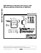
Figure 1a. MAX1833/MAX1835 Typical Operating Circuit
Figure 1b. MAX1832/MAX1834 Typical Operating Circuit