
User guide


MAX186/MAX188
Low-Power, 8-Channel,
Serial 12-Bit ADCs
______________________________________________________________________________________ 21
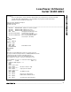
*Title : MAX186.ASM
* Description :
* This is a shell program for using a stand-alone 68HC16 without any external memory. The internal 1K RAM
* is put into bank $0F to maintain 68HC11 code compatibility. This program was written with software
* provided in the Motorola 68HC16 Evaluation Kit.
*
* Roger J.A. Chen, Applications Engineer
* MAXIM Integrated Products
* November 20, 1992
*
******************************************************************************************************************************************************
INCLUDE ‘EQUATES.ASM’ ;Equates for common reg addrs
INCLUDE ‘ORG00000.ASM’ ;initialize reset vector
INCLUDE ‘ORG00008.ASM’ ;initialize interrupt vectors
ORG $0200 ;start program after interrupt vectors
INCLUDE ‘INITSYS.ASM’ ;set EK=F,XK=0,YK=0,ZK=0
;set sys clock at 16.78 MHz, COP off
INCLUDE ‘INITRAM.ASM’ ;turn on internal SRAM at $10000
;set stack (SK=1, SP=03FE)
MAIN:
JSR INITQSPI
MAINLOOP:
JSR READ186
WAIT:
LDAA SPSR
ANDA #$80
BEQ WAIT ;wait for QSPI to finish
BRA MAINLOOP
ENDPROGRAM:
INITQSPI:
;This routine sets up the QSPI microsequencer to operate on its own.
;The sequencer will read all eight channels of a MAX186/MAX188 each time
;it is triggered. The A/D converter results will be left in the
;receive data RAM. Each 16 bit receive data RAM location will
;have a leading zero, 12 bits of conversion result and three zeros.
;
;Receive RAM Bits 15 14 13 12 11 10 09 08 07 06 05 04 03 02 01 00
;A/D Result 0 MSB LSB 0 0 0
***** Initialize the QSPI Registers ******
PSHA
PSHB
LDAA #%01111000
STAA QPDR ;idle state for PCS0-3 = high
LDAA #%01111011
STAA QPAR ;assign port D to be QSPI
LDAA #%01111110
STAA QDDR ;only MISO is an input
LDD #$8008
STD SPCR0 ;master mode,16 bits/transfer,
;CPOL=CPHA=0,1MHz Ser Clock
LDD #$0000
STD SPCR1 ;set delay between PCS0 and SCK,
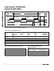
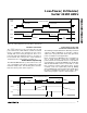
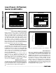
Figure 20. MAX186/MAX188 Assembly-Code Listing