
Owner's manual

Control Scheme
The MAX1947 is a bootstrapped design. Upon turn-on,
a startup oscillator brings the output voltage high
enough to allow the main DC-DC circuitry to run. Once
the output voltage reaches 1.62V (typ) the main DC-DC
circuitry turns on and boosts the output voltage to the
final regulation point.
The unique minimum off-time, current-limited control
scheme is the key to the MAX1947’s low operating cur-
rent and high efficiency over a wide load range. The
architecture combines the high output power and effi-
ciency of a pulse-width modulation (PWM) device with
the ultra-low quiescent current of a traditional pulse-
skipping controller. The switching frequency can be as
high as 2MHz and depends upon the load current and
input voltage. The MAX1947 is designed to operate
using low-ESR ceramic capacitors, so output voltage
ripple due to ESR is very small (approximately 10mV
P-P
).
Track Mode
The MAX1947 enters track mode when BATT is greater
than the output-voltage regulation point. Track mode
can only be entered under the following conditions:
V
BATT
> V
OUT
, V
OUT
> V
OUT
regulation point, and the
minimum off-time expires. During track mode, the syn-
chronous rectifier is turned on 100% of the time and the
output voltage tracks the battery voltage. Track mode is
exited by V
OUT
falling below the V
OUT
regulation point.
Synchronous Rectification
The internal synchronous rectifier eliminates the need
for an external Schottky diode, reducing cost and board
space. During the cycle off-time, the p-channel MOSFET
turns on and shunts the MOSFET body diode. As a
result, the synchronous rectifier significantly improves
efficiency without the addition of an external compo-
nent. Conversion efficiency can be as high as 94%.
RESET
The MAX1947 features an active-low push-pull RESET
output for use with a microcontroller (µC). It signals the
µC when the MAX1947 output voltage is within operat-
ing limits. During startup, RESET is held low. When the
RESET threshold (90% of the output regulation voltage)
is reached, a 75ms (min) timer begins counting. RESET
is switched high once the timer expires.
MAX1947
Low Input/Output Voltage
Step-Up DC-DC Converter with
RESET
_______________________________________________________________________________________ 7
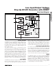
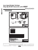
Functional Diagram
STARTUP
OSCILLATOR
SHUTDOWN
CIRCUITRY
t
ON
MAX TIMER
CONTROL
LOGIC AND
GATE DRIVERS
BATT
SHDN
0.9 x REF
REF
ERROR
AMPLIFIER
ZERO-CROSSING
AMPLIFIER
CURRENT-LIMIT
AMPLIFIER
P*
N
LX
PGND
OUT
RESET
75ms TIMER
t
OFF
MIN TIMER
1.25V REFERENCE
(REF)
GND
MAX1947
REF
*BODY DIODE CONTROL