
Owner's manual

Calculate the maximum output current (I
OUTMAX
) using
inductor ripple current (I
RIPPLE
) and duty cycle (D) as
follows:
Here, I
LIM
is the NFET current limit (800mA typ), t
OFF
is
the LX switch’s off-time (0.25µs typ), and R
L
is the
series resistance of the inductor.
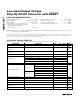
Capacitor Selection
The MAX1947 is specifically designed for using small,
inexpensive, low-ESR ceramic capacitors. X5R and
X7R dielectrics are recommended when operating over
wide temperature ranges. Bypass the output of the
MAX1947 with 10µF when using maximum load cur-
rents. When using less than half the maximum load cur-
rent capability, the output capacitor can be reduced to
4.7µF. Bypass the input with a 2.2µF or larger ceramic
capacitor. Table 1 lists the suggested values for the
input and output capacitors for typical applications.
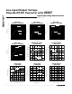
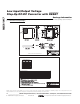
PC Board Layout and Grounding
Careful printed circuit-board layout is important for min-
imizing ground bounce and noise. Keep the IC’s GND
pins and the ground leads of the input and output filter
capacitors very close together. Connect GND and
PGND directly to the exposed paddle. In addition, keep
all connections to the OUT and LX pins as short as pos-
sible. To maximize output power and efficiency and
minimize output ripple voltage, use short, wide traces
from the input and output. A sample layout is available
in the MAX1947 evaluation kit.
Chip Information
TRANSISTOR COUNT: 5156
PROCESS: BiCMOS
MAX1947
Low Input/Output Voltage
Step-Up DC-DC Converter with
RESET
_______________________________________________________________________________________ 9
I
VIR RV
Lt
RR
D
VI
LIM
I
RIPPLE
R
DS ON PFET
RV
VI
LIM
I
RIPPLE
R
DS ON PFET
RR
RIPPLE
OUT LIM DS ON PFET L BATT
OFF
DS ON PFET L
OUT
L BATT
OUT
DS ON NFET L
=
+× +−
+
+
=
+ − ×
+ −
+ − ×
− +
()
/
()
()
(
()
)
()
(
()
)
()
()
()
2
2
2
= − × −II
LIM
I
RIPPLE
D
OUTMAX
()()
2
1