9-4827; Rev 0; 10/09 TION KIT EVALUA BLE AVAILA SiGe, High-Linearity, 2300MHz to 4000MHz Downconversion Mixer with LO Buffer Features The MAX19998 single, high-linearity downconversion mixer provides 8.7dB of conversion gain, +24.3dBm input IP3, +11.3dBm 1dB input compression point, and a noise figure of 9.7dB for 2300MHz to 4000MHz WiMAXK, LTE, and MMDS receiver applications.
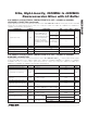
MAX19998 SiGe, High-Linearity, 2300MHz to 4000MHz Downconversion Mixer with LO Buffer ABSOLUTE MAXIMUM RATINGS VCC to GND...........................................................-0.3V to +5.5V IF+, IF-, LOBIAS, IFBIAS to GND.............. -0.3V to (VCC + 0.3V) RF, LO Input Power........................................................ +12dBm RF, LO Current (RF and LO is DC shorted to GND through balun).........50mA Continuous Power Dissipation (Note 1)..................................
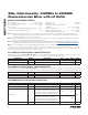
SiGe, High-Linearity, 2300MHz to 4000MHz Downconversion Mixer with LO Buffer (Typical Application Circuit, with tuning elements outlined in Table 1, R1 = 698ω, R2 = 604ω, VCC = 4.75V to 5.25V, RF and LO ports are driven from 50I sources, PLO = -3dBm to +3dBm, PRF = -5dBm, fRF = 3100MHz to 3900MHz, fIF = 300MHz, fLO = 2800MHz to 3600MHz, fRF > fLO, TC = -40NC to +85NC. Typical values are for TC = +25NC, VCC = 5.0V, PRF = -5dBm, PLO = 0dBm, fRF = 3500MHz, fLO = 3200MHz, fIF = 300MHz.
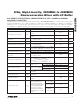
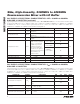
MAX19998 SiGe, High-Linearity, 2300MHz to 4000MHz Downconversion Mixer with LO Buffer 5.0V SUPPLY AC ELECTRICAL CHARACTERISTICS—fRF = 3100MHz to 3900MHz, LOW-SIDE LO INJECTION (continued) (Typical Application Circuit, with tuning elements outlined in Table 1, R1 = 698ω, R2 = 604ω, VCC = 4.75V to 5.25V, RF and LO ports are driven from 50I sources, PLO = -3dBm to +3dBm, PRF = -5dBm, fRF = 3100MHz to 3900MHz, fIF = 300MHz, fLO = 2800MHz to 3600MHz, fRF > fLO, TC = -40NC to +85NC.
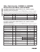
SiGe, High-Linearity, 2300MHz to 4000MHz Downconversion Mixer with LO Buffer (Typical Application Circuit, with tuning elements outlined in Table 1, R1 = 845ω, R2 = 1.1kω, RF and LO ports are driven from 50I sources, fRF > fLO. Typical values are for TC = +25NC, VCC = 3.3V, PRF = -5dBm, PLO = 0dBm, fRF = 3500MHz, fLO = 3200MHz, fIF = 300MHz, unless otherwise noted.
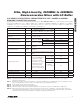
MAX19998 SiGe, High-Linearity, 2300MHz to 4000MHz Downconversion Mixer with LO Buffer 5.0V SUPPLY AC ELECTRICAL CHARACTERISTICS—fRF = 3100MHz to 3900MHz, HIGH-SIDE LO INJECTION (continued) (Typical Application Circuit, with tuning elements outlined in Table 1, R1 = 698ω, R2 = 604ω, VCC = 4.75V to 5.25V, RF and LO ports are driven from 50I sources, PLO = -3dBm to +3dBm, PRF = -5dBm, fRF = 3100MHz to 3900MHz, fIF = 300MHz, fLO = 3400MHz to 4200MHz, fRF < fLO, TC = -40NC to +85NC.
SiGe, High-Linearity, 2300MHz to 4000MHz Downconversion Mixer with LO Buffer (Typical Application Circuit, with tuning elements outlined in Table 1, R1 = 698ω, R2 = 604ω, VCC = 4.75V to 5.25V, RF and LO ports are driven from 50I sources, PLO = -3dBm to +3dBm, PRF = -5dBm, fRF = 2300MHz to 2900MHz, fIF = 300MHz, fLO = 2600MHz to 3200MHz, fRF < fLO, TC = -40NC to +85NC. Typical values are for TC = +25NC, VCC = 5.0V, PRF = -5dBm, PLO = 0dBm, fRF = 2600MHz, fLO = 2900MHz, fIF = 300MHz, unless otherwise noted.
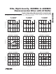
Typical Operating Characteristics (Typical Application Circuit with tuning elements outlined in Table 1, VCC = 5.0V, fRF = 3100MHz to 3900MHz, LO is low-side injected for a 300MHz IF, PRF = -5dBm, PLO = 0dBm, TC = +25NC, unless otherwise noted.) TC = +85°C 7 8 PLO = -3dBm, 0dBm, +3dBm 7 6 3400 3600 3800 4000 3200 RF FREQUENCY (MHz) 3600 3800 4000 3000 24 25 24 23 3400 3600 3800 4000 3800 VCC = 5.25V PLO = -3dBm, 0dBm, +3dBm 25 24 VCC = 5.0V VCC = 4.
SiGe, High-Linearity, 2300MHz to 4000MHz Downconversion Mixer with LO Buffer TC = -40°C, +25°C, +85°C 65 55 75 PLO = -3dBm, 0dBm, +3dBm 65 55 3400 3600 3800 4000 VCC = 4.75V, 5.0V, 5.25V 65 3200 3400 3600 3800 4000 3000 3200 RF FREQUENCY (MHz) NOISE FIGURE vs. RF FREQUENCY NOISE FIGURE vs. RF FREQUENCY TC = +85°C TC = +25°C 8 3800 4000 NOISE FIGURE vs.
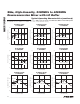
Typical Operating Characteristics (continued) (Typical Application Circuit with tuning elements outlined in Table 1, VCC = 5.0V, fRF = 3100MHz to 3900MHz, LO is low-side injected for a 300MHz IF, PRF = -5dBm, PLO = 0dBm, TC = +25NC, unless otherwise noted.) LO LEAKAGE AT IF PORT vs. LO FREQUENCY TC = +85°C -20 TC = +25°C TC = -40°C -40 2900 3100 3300 3500 3700 -40 2700 2900 3100 3300 3500 3700 2700 2900 3100 3300 3500 LO FREQUENCY (MHz) RF-TO-IF ISOLATION vs.
SiGe, High-Linearity, 2300MHz to 4000MHz Downconversion Mixer with LO Buffer 2LO LEAKAGE AT RF PORT vs. LO FREQUENCY TC = +85°C -40 -50 -30 -40 PLO = -3dBm, 0dBm, +3dBm -50 3000 3500 4000 -30 -40 VCC = 4.75V, 5.0V, 5.25V -50 3000 2500 LO FREQUENCY (MHz) 3500 4000 3000 2500 LO FREQUENCY (MHz) 20 30 0 IF PORT RETURN LOSS (dB) fIF = 300MHz 10 4000 IF PORT RETURN LOSS vs. IF FREQUENCY MAX19998 toc31 0 3500 LO FREQUENCY (MHz) RF PORT RETURN LOSS vs.
Typical Operating Characteristics (continued) (Typical Application Circuit with tuning elements outlined in Table 1, VCC = 3.3V, fRF = 3100MHz to 3900MHz, LO is low-side injected for a 300MHz IF, PRF = -5dBm, PLO = 0dBm, TC = +25NC, unless otherwise noted.) TC = +85NC 6 8 PLO = -3dBm, 0dBm, +3dBm 7 6 3400 3600 3800 4000 3200 RF FREQUENCY (MHz) TC = +85NC 20 TC = +25NC 3600 3800 4000 TC = -40NC 18 3600 3800 VCC = 3.3V PRF = -5dBm/TONE 20 PLO = -3dBm, 0dBm, +3dBm 4000 3800 21 VCC = 3.
SiGe, High-Linearity, 2300MHz to 4000MHz Downconversion Mixer with LO Buffer TC = -40°C, +25°C, +85°C 55 65 60 PLO = -3dBm, 0dBm, +3dBm 55 50 3400 3600 3800 4000 3200 RF FREQUENCY (MHz) NOISE FIGURE vs. RF FREQUENCY TC = -40NC 3600 3800 4000 VCC = 3.6V 3000 MAX19998 toc47 VCC = 3.3V 11 3200 10 9 3600 3800 4000 9 7 3000 3200 RF FREQUENCY (MHz) INPUT P1dB vs. RF FREQUENCY 4000 3000 3200 TC = +25NC 3400 3600 3800 4000 RF FREQUENCY (MHz) VCC = 3.
Typical Operating Characteristics (continued) (Typical Application Circuit with tuning elements outlined in Table 1, VCC = 3.3V, fRF = 3100MHz to 3900MHz, LO is low-side injected for a 300MHz IF, PRF = -5dBm, PLO = 0dBm, TC = +25NC, unless otherwise noted.) -30 TC = -40°C, +25°C, +85°C -40 -50 -30 PLO = -3dBm, 0dBm, +3dBm -40 -50 2900 3100 3300 3500 3700 -30 VCC = 3.0V VCC = 3.
SiGe, High-Linearity, 2300MHz to 4000MHz Downconversion Mixer with LO Buffer 2LO LEAKAGE AT RF PORT vs. LO FREQUENCY TC = -40NC -30 TC = +85NC -10 -20 -30 PLO = -3dBm, 0dBm, +3dBm -40 -50 VCC = 3.0V -30 VCC = 3.3V -40 3500 4000 -50 2500 3000 LO FREQUENCY (MHz) 3500 4000 2500 3000 LO FREQUENCY (MHz) 3500 4000 LO FREQUENCY (MHz) RF PORT RETURN LOSS vs. RF FREQUENCY IF PORT RETURN LOSS vs. IF FREQUENCY 0 MAX19998 toc65 0 VCC = 3.
Typical Operating Characteristics (continued) (Typical Application Circuit with tuning elements outlined in Table 1, VCC = 5.0V, fRF = 3100MHz to 3900MHz, LO is high-side injected for a 300MHz IF, PRF = -5dBm, PLO = 0dBm, TC = +25NC, unless otherwise noted.
SiGe, High-Linearity, 2300MHz to 4000MHz Downconversion Mixer with LO Buffer TC = +25°C TC = -40°C 65 55 75 PLO = -3dBm, 0dBm, +3dBm 65 55 3200 3400 3600 3800 4000 3200 RF FREQUENCY (MHz) NOISE FIGURE vs. RF FREQUENCY 3400 3600 3800 VCC = 4.75V, 5.0V, 5.25V 65 4000 3000 3200 NOISE FIGURE vs. RF FREQUENCY TC = +25°C 11 8 3600 3800 4000 NOISE FIGURE vs.
Typical Operating Characteristics (continued) (Typical Application Circuit with tuning elements outlined in Table 1, VCC = 5.0V, fRF = 3100MHz to 3900MHz, LO is high-side injected for a 300MHz IF, PRF = -5dBm, PLO = 0dBm, TC = +25NC, unless otherwise noted.) LO LEAKAGE AT IF PORT vs.
SiGe, High-Linearity, 2300MHz to 4000MHz Downconversion Mixer with LO Buffer 2LO LEAKAGE AT RF PORT vs. LO FREQUENCY -20 PLO = -3dBm -30 PLO = 0dBm -40 -40 3800 4050 3800 4050 4300 3550 3300 LO FREQUENCY (MHz) LO FREQUENCY (MHz) 20 0 fLO = 4100MHz IF PORT RETURN LOSS (dB) fIF = 300MHz 10 4050 4300 IF PORT RETURN LOSS vs. IF FREQUENCY MAX19998 toc99 0 3800 LO FREQUENCY (MHz) RF PORT RETURN LOSS vs. RF FREQUENCY 30 VCC = 4.75V, 5.0V, 5.
Typical Operating Characteristics (continued) (Typical Application Circuit with tuning elements outlined in Table 1, VCC = 5.0V, fRF = 2300MHz to 2900MHz, LO is high-side injected for a 300MHz IF, PRF = -5dBm, PLO = 0dBm, TC = +25NC, unless otherwise noted.) 8 8 PLO = -3dBm, 0dBm, +3dBm 2750 2900 RF FREQUENCY (MHz) INPUT IP3 vs. RF FREQUENCY 2600 2750 2900 2300 26 25 PLO = -3dBm, 0dBm, +3dBm 24 TC = -40°C 23 2450 2600 2750 2900 26 25 VCC = 5.0V 24 VCC = 4.
SiGe, High-Linearity, 2300MHz to 4000MHz Downconversion Mixer with LO Buffer TC = +25NC TC = -40NC 65 55 75 PLO = -3dBm, 0dBm, +3dBm 65 55 2600 2750 2900 TC = +25NC 10 TC = -40NC 2600 2750 2900 2300 11 2600 2750 PLO = -3dBm, 0dBm, +3dBm 10 2900 12 2450 2600 2750 2900 12 9 2750 RF FREQUENCY (MHz) 2900 2600 2750 2900 INPUT P1dB vs. RF FREQUENCY 11 PLO = -3dBm, 0dBm, +3dBm 13 VCC = 5.25V VCC = 5.0V 12 11 VCC = 4.
Typical Operating Characteristics (continued) (Typical Application Circuit with tuning elements outlined in Table 1, VCC = 5.0V, fRF = 2300MHz to 2900MHz, LO is high-side injected for a 300MHz IF, PRF = -5dBm, PLO = 0dBm, TC = +25NC, unless otherwise noted.) TC = +25°C TC = +85°C -30 TC = -40°C -40 -30 PLO = -3dBm, 0dBm, +3dBm 2750 2900 3050 3200 VCC = 4.75V, 5.0V, 5.25V -40 2600 2750 2900 3050 3200 2600 2750 2900 3050 LO FREQUENCY (MHz) RF-TO-IF ISOLATION vs.
SiGe, High-Linearity, 2300MHz to 4000MHz Downconversion Mixer with LO Buffer 2LO LEAKAGE AT RF PORT vs. LO FREQUENCY TC = +85NC -50 -60 PLO = +3dBm -40 PLO = 0dBm -50 PLO = -3dBm -60 3000 3500 4000 VCC = 4.75V -40 VCC = 5.25V -50 3500 4000 3000 2500 LO FREQUENCY (MHz) 20 30 0 fLO = 3000MHz IF PORT RETURN LOSS (dB) fIF = 300MHz 4000 IF PORT RETURN LOSS vs. IF FREQUENCY MAX19998 toc133 0 3500 LO FREQUENCY (MHz) RF PORT RETURN LOSS vs. RF FREQUENCY 10 VCC = 5.
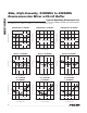
MAX19998 SiGe, High-Linearity, 2300MHz to 4000MHz Downconversion Mixer with LO Buffer VCC 1 RF 2 GND IF+ IF- GND LEXT TOP VIEW IFBIAS Pin Configuration/Functional Diagram 20 19 18 17 16 15 GND 14 VCC 3 13 GND GND 4 12 GND GND 5 11 LO MAX19998 6 7 8 9 10 VCC LOBIAS VCC GND GND EP Pin Description PIN NAME 1, 6, 8, 14 VCC FUNCTION 2 RF 3, 9, 13, 15 GND Ground. Not internally connected. Pins can be grounded. 4, 5, 10, 12, 17 GND Ground.
SiGe, High-Linearity, 2300MHz to 4000MHz Downconversion Mixer with LO Buffer The MAX19998 provides high linearity and low noise figure for a multitude of 2300MHz to 4000MHz WiMAX, LTE, and MMDS base-station applications. This device operates over a 2600MHz to 4300MHz LO range and a 50MHz to 500MHz IF range. Integrated baluns and matching circuitry allow 50I single-ended interfaces to the RF and LO ports.
MAX19998 SiGe, High-Linearity, 2300MHz to 4000MHz Downconversion Mixer with LO Buffer LEXT Inductor Short LEXT to ground using a 0I resistor. For applications requiring improved RF-to-IF and LO-to-IF isolation, L3 can be changed to optimize performance (see the Typical Operating Characteristics). However, the load impedance presented to the mixer must be such that any capacitances from IF- and IF+ to ground do not exceed several picofarads to ensure stable operating conditions.
SiGe, High-Linearity, 2300MHz to 4000MHz Downconversion Mixer with LO Buffer heat from the EP. In addition, provide the EP with a lowinductance path to electrical ground. The EP MUST be soldered to a ground plane on the PCB, either directly or through an array of plated via holes.
MAX19998 SiGe, High-Linearity, 2300MHz to 4000MHz Downconversion Mixer with LO Buffer Chip Information PROCESS: SiGe BiCMOS Package Information For the latest package outline information and land patterns, go to www.maxim-ic.com/packages. Note that a “+”, “#”, or “-” in the package code indicates RoHS status only. Package drawings may show a different suffix character, but the drawing pertains to the package regardless of RoHS status. PACKAGE TYPE PACKAGE CODE DOCUMENT NO.