9-5527; Rev 0; 9/10 PMBus 6-Channel Power-Supply Manager The MAX34440 is a complex system monitor that can manage up to six power supplies. The power-supply manager monitors the power-supply output voltage and constantly checks for user-programmable overvoltage and undervoltage thresholds. It can also margin the power-supply output voltage up or down to a userprogrammable level.
MAX34440 PMBus 6-Channel Power-Supply Manager TABLE OF CONTENTS Absolute Maximum Ratings . . . . . . . . . . . . . . . . . . . . . . . . . . . . . . . . . . . . . . . . . . . . . . . . . . . . . . . . . . . . . . . . . . . . . . . 6 Recommended Operating Conditions . . . . . . . . . . . . . . . . . . . . . . . . . . . . . . . . . . . . . . . . . . . . . . . . . . . . . . . . . . . . . . . 6 DC Electrical Characteristics . . . . . . . . . . . . . . . . . . . . . . . . . . . . . . . . . . . . . . . . . . . .
PMBus 6-Channel Power-Supply Manager PMBus Commands . . . . . . . . . . . . . . . . . . . . . . . . . . . . . . . . . . . . . . . . . . . . . . . . . . . . . . . . . . . . . . . . . . . . . . . . . . . . 23 PAGE (00h) . . . . . . . . . . . . . . . . . . . . . . . . . . . . . . . . . . . . . . . . . . . . . . . . . . . . . . . . . . . . . . . . . . . . . . . . . . . . . . . . 23 OPERATION (01h) . . . . . . . . . . . . . . . . . . . . . . . . . . . . . . . . . . . . . . . . . . . . . . . . . . . . . . . .
MAX34440 PMBus 6-Channel Power-Supply Manager TABLE OF CONTENTS (continued) MFR_MODEL (9Ah) . . . . . . . . . . . . . . . . . . . . . . . . . . . . . . . . . . . . . . . . . . . . . . . . . . . . . . . . . . . . . . . . . . . . . . . . . 34 MFR_REVISION (9Bh) . . . . . . . . . . . . . . . . . . . . . . . . . . . . . . . . . . . . . . . . . . . . . . . . . . . . . . . . . . . . . . . . . . . . . . . 34 MFR_LOCATION (9Ch) . . . . . . . . . . . . . . . . . . . . . . . . . . . . . . . . . . . . . . . . . .
PMBus 6-Channel Power-Supply Manager Figure 1. Power-Supply Sequencing . . . . . . . . . . . . . . . . . . . . . . . . . . . . . . . . . . . . . . . . . . . . . . . . . . . . . . . . . . . . . . . 30 Figure 2. MFR_NV_FAULT_LOG . . . . . . . . . . . . . . . . . . . . . . . . . . . . . . . . . . . . . . . . . . . . . . . . . . . . . . . . . . . . . . . . . . 38 LIST OF TABLES Table 1. PMBus Command Codes . . . . . . . . . . . . . . . . . . . . . . . . . . . . . . . . . . . . . . . . . . . . . . . . . . . .
MAX34440 PMBus 6-Channel Power-Supply Manager ABSOLUTE MAXIMUM RATINGS VDD to VSS............................................................-0.3V to +5.5V RS- to VSS.............................................................-0.3V to +0.3V All Other Pins Except REG18 and REG25 Relative to VSS......................... -0.3V to (VDD + 0.3V)* Continuous Power Dissipation (TA = +70NC) 40-Pin TQFN (derate 35.7mW/NC above +70NC)..........................2857.1mW Operating Temperature Range....................
PMBus 6-Channel Power-Supply Manager (VDD = 2.7V to 5.5V, TA = -40NC to +85NC, unless otherwise noted. Typical values are at VDD = 3.3V, TA = +25NC, unless otherwise noted.) PARAMETER SYMBOL CONDITIONS ADC Internal Reference Initial Accuracy (+25NC) VFS ADC Measurement Resolution VLSB 1.213 1.225 MAX UNITS +1 mV 1.
MAX34440 PMBus 6-Channel Power-Supply Manager I2C/SMBus INTERFACE ELECTRICAL SPECIFICATIONS (VDD = 2.7V to 5.5V, TA = -40NC to +85NC, unless otherwise noted. Typical values are at VDD = 3.3V, TA = +25NC, unless otherwise noted.) PARAMETER SYMBOL CONDITIONS MIN TYP MAX UNITS 100 kHz SCL Clock Frequency fSCL 10 Bus Free Time Between STOP and START Conditions tBUF 4.7 Fs Hold Time (Repeated) START Condition tHD:STA 4.0 Fs Low Period of SCL tLOW 4.7 Fs High Period of SCL tHIGH 4.
PMBus 6-Channel Power-Supply Manager (TA = +25°C, unless otherwise noted.) SUPPLY CURRENT vs. SUPPLY VOLTAGE SUPPLY CURRENT vs. TEMPERATURE 2.5 2.5 2.4 IDD (mA) 2.4 IDD (mA) MAX34440 toc02 2.6 MAX34440 toc01 2.6 2.3 VDD = 3.3V 2.3 TA = +25°C 2.2 2.2 2.1 2.1 2.0 2.0 -40 -20 0 20 40 60 80 2.7 100 3.1 3.5 3.9 4.3 4.7 5.1 5.5 TEMPERATURE (°C) VDD (V) WEAK PULLUP VOLTAGE vs. TIME AT POR (UNLOADED PINS, VDD = 3.3V) IDD vs.
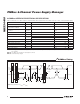
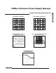
PMBus 6-Channel Power-Supply Manager VSS REG18 PSEN3 PWM2 PWM1 PSEN2 PSEN1 PWM0 TOP VIEW REG25 PSEN0 MAX34440 Pin Configuration 30 29 28 27 26 25 24 23 22 21 SDA 31 20 PWM3 SCL 32 19 PSEN4 A0/MUXSEL 33 18 PWM4 FAULT 34 17 PSEN5 CONTROL 35 16 PWM5 MAX34440 VSS 36 15 MSCL A1/PG 37 14 MSDA ALERT 38 RS-5 39 13 RST EP + 12 RS-2 11 RS+2 5 6 VSS RS+4 RS-3 RS+3 RS+0 7 8 9 10 RS-1 4 VDD 3 RS-0 2 RS+1 1 RS-4 RS+5 40 TQFN (6mm × 6mm × 0.
PMBus 6-Channel Power-Supply Manager PIN NAME FUNCTION 18 PWM4 PWM Margin Output #4. High impedance when the margining is disabled. A 100% duty cycle implies this pin is continuously high. 19 PSEN4 Power-Supply Enable Output #4. Programmable through MFR_MODE for either active high or active low and either open drain or CMOS push-pull. 20 PWM3 PWM Margin Output #3. High impedance when the margining is disabled. A 100% duty cycle implies this pin is continuously high.
Pin Description (continued) PIN NAME 39 RS-5 Ground Reference for ADC5 Voltage Measurement FUNCTION 40 RS+5 Power-Supply ADC Voltage-Sense Input, Measurement Relative to RS-5 — EP Exposed Pad (Bottom Side of Package). Connect EP to VSS. Note: All pins except VDD, VSS, REG18, REG25, ADC, and the EP are high impedance with a 50µA pullup during device power-up and reset. After device reset, the weak pullup is removed, and the pin is configured as input or output.
PMBus 6-Channel Power-Supply Manager +3.3V ALERT HOST INTERFACE CLOCK DATA CONTROL RST SDA SCL RST ALERT MAX34440 #0 FAULT CONTROL A1/PG A0/MUXSEL +3.
MAX34440 PMBus 6-Channel Power-Supply Manager Detailed Description the supplies in any order at both power-up and powerdown. With the addition of an external current-sense amplifier, the device can also monitor currents. The MAX34440 is a highly integrated system monitor based upon a 16-bit MAXQM microcontroller with factory-programmed functionality to monitor up to six power supplies. The device provides power-supply closed-loop control, and local/remote thermal-sensing facilities.
PMBus 6-Channel Power-Supply Manager CODE COMMAND NAME TYPE PAGE 0–5 PAGE 6–13 PAGE 255 (NOTE 1) NO.
MAX34440 PMBus 6-Channel Power-Supply Manager Table 2. PMBus/SMBus Serial-Port Address 7-BIT SLAVE ADDRESS A1 A0 100kI to VSS 100kI to VSS 100kI to VDD 100kI to VDD Address Select On device power-up, the device samples the A0 and A1 pins to determine the PMBus/SMBus serial-port address. SMBus/PMBus Operation 1101 010 (D4h) The device implements the PMBus command structure using the SMBus format.
PMBus 6-Channel Power-Supply Manager continuous data stream. All the devices addressed during this transaction wait for the host to issue a STOP before beginning to respond to the command.
MAX34440 PMBus 6-Channel Power-Supply Manager Alert Response Address (ARA) Byte Format 1 7 S ARA 0001100 1 R 1 8 1 1 A DEVICE SLAVE ADDRESS WITH LSB = 0 NA P Host Sends or Reads Too Few Bits If for any reason the host does not complete writing a full byte or reading a full byte from the device before a START or STOP is received, the device does the following: 1) Ignores the command. 2) Sets the CML bit in STATUS_BYTE. 3) Sets the CML bit in STATUS_WORD.
PMBus 6-Channel Power-Supply Manager 1) ACKs the address byte. 2) Ignores the command. 3) Sends all ones (FFh) as long as the host keeps acknowledging. 4) Sets the CML bit in STATUS_BYTE. 5) Sets the CML bit in STATUS_WORD. 6) Sets the DATA_FAULT bit in STATUS_CML. 7) Notifies the host through ALERT assertion (if enabled). Host Writes to a Read-Only Command When a write request is issued to a read-only command, the device does the following: 1) Ignores the command. 2) Sets the CML bit in STATUS_BYTE.
MAX34440 PMBus 6-Channel Power-Supply Manager Table 3.
PMBus 6-Channel Power-Supply Manager See the individual command sections for more details. Faults and warnings that are latched in the status registers are cleared when any one of the following conditions occurs: • A CLEAR_FAULTS command is received. • The RST pin is toggled. • Bias power to the device is removed and then reapplied.
MAX34440 PMBus 6-Channel Power-Supply Manager Temperature Sensor Operation The device can monitor up to eight different temperature sensors, seven external sensors plus its own internal temperature sensor. The external temperature sensors are all connected in parallel to the master I2C port (MSDA and MSCL pins). The device can support up to four DS75LV devices plus one MAX6695 device. Each of the enabled temperature sensors is measured once a second.
PMBus 6-Channel Power-Supply Manager A summary of the PMBus commands supported by the device are described in the following sections. PAGE (00h) The device can control up to six power supplies and up to eight temperature sensors using one PMBus (I2C) address. Send the PAGE command with data 0 to 13 to select which power supply or which temperature sensor is affected by all the PMBus commands shown in Table 1. Not all commands are supported within each page.
MAX34440 PMBus 6-Channel Power-Supply Manager OPERATION (01h) The OPERATION command is used to turn the power supply on and off in conjunction with the CONTROL input pin. The OPERATION command is also used to cause the power supply to set the output voltage to the upper or lower margin voltages. The power supply stays in the commanded operating mode until a subsequent OPERATION command or until a change in the state of the CONTROL pin (if enabled) instructs the power supply to change to another state.
PMBus 6-Channel Power-Supply Manager Table 10. ON_OFF_CONFIG (02h) Command Byte BIT 7:5 4 PURPOSE Reserved BIT VALUE N/A Turn on supplies when bias is present or use the CONTROL pin and/or OPERATION command 3 OPERATION Command Enable 2 CONTROL Pin Enable 1 CONTROL Pin Polarity 0 CONTROL Pin Turn-Off Action MEANING Always returns 000. 0 Turn on the supplies (with sequencing, if so configured) as soon as bias is supplied to the device regardless of the CONTROL pin.
MAX34440 PMBus 6-Channel Power-Supply Manager STORE_DEFAULT_ALL (11h) The STORE_DEFAULT_ALL command instructs the device to transfer the device configuration information to the internal flash memory array. Not all information is stored. Only configuration data is stored, not any status, or operational data. If an error occurs during the transfer, ALERT asserts if enabled and the CML bit in STATUS_BYTE and STATUS_WORD is set to 1. No bits are set in STATUS_CML.
PMBus 6-Channel Power-Supply Manager 1) Sets the NONE OF THE ABOVE bit in STATUS_BYTE. 2) Sets the NONE OF THE ABOVE and MFR bits in STATUS_WORD. 3) Sets the MARGIN_FAULT bit in STATUS_MFR_SPECIFIC. 4) Notifies the host through ALERT assertion (if enabled in MFR_MODE). VOUT_SCALE_MONITOR (2Ah) VOUT_SCALE_MONITOR is used in applications where the measured power-supply voltage is not equal to the voltage at the ADC input. For example, if the ADC input expects a 1.
MAX34440 PMBus 6-Channel Power-Supply Manager VOUT_OV_FAULT_LIMIT (40h) The VOUT_OV_FAULT_LIMIT command sets the value of the output voltage that causes an output overvoltage fault. The 2 data bytes are in DIRECT format. In response to the VOUT_OV_FAULT_LIMIT being exceeded, the device does the following: 1) Sets the VOUT_OV bit in STATUS_BYTE. 2) Sets the VOUT_OV and VOUT bits in STATUS_WORD. 3) Sets the VOUT_OV_FAULT bit in STATUS_VOUT. 4) Responds as specified in the MFR_FAULT_RESPONSE.
PMBus 6-Channel Power-Supply Manager 1) Sets the NONE OF THE ABOVE bit in STATUS_BYTE. 2) Sets the NONE OF THE ABOVE, IOUT, and MFR bits in STATUS_WORD. 3) Sets the OC_WARN bit in STATUS_MFR_SPECIFIC. 4) Notifies the host using ALERT assertion (if enabled in MFR_MODE). IOUT_OC_FAULT_LIMIT (4Ah) The IOUT_OC_FAULT_LIMIT command sets the value of the current that causes an overcurrent fault. The factory default value for IOUT_OC_FAULT_LIMIT is 0000h. This value disables the device from measuring current.
MAX34440 PMBus 6-Channel Power-Supply Manager OT_WARN_LIMIT (51h) The OT_WARN_LIMIT command sets the temperature, in degrees Celsius, of the selected temperature sensor at which an overtemperature warning is detected. The 2 data bytes are in DIRECT format. In response to the OT_WARN_LIMIT being exceeded, the device does the following: 1) Sets the TEMPERATURE bit in STATUS_BYTE. 2) Sets the TEMPERATURE and MFR bits in STATUS_WORD. 3) Sets the OT_WARN bit in STATUS_MFR_SPECIFIC.
PMBus 6-Channel Power-Supply Manager When the VOUT level of a power supply falls from greater than POWER_GOOD_ON to less than POWER_GOOD_OFF, the device does the following: 1) Sets the NONE OF THE ABOVE bit in STATUS_BYTE. 2) Sets the NONE OF THE ABOVE, POWER_GOOD#, and STATUS_MFR_SPECIFIC bits in STATUS_WORD. 3) Sets the POWER_GOOD# bit in STATUS_MFR_SPECIFIC.
MAX34440 PMBus 6-Channel Power-Supply Manager STATUS_BYTE (78h) The STATUS_BYTE command returns 1 byte of information with a summary of the most critical faults. A value of 1 indicates that a fault or warning event has occurred and a 0 indicates otherwise. Bits for unsupported features are reported as 0. The STATUS_BYTE cannot be restored by the RESTORE_DEFAULT_ALL command. The STATUS_BYTE message content is described in Table 16. This command is read-only. Table 16.
PMBus 6-Channel Power-Supply Manager Table 18. STATUS_VOUT BIT BIT NAME 7 VOUT_OV_FAULT VOUT overvoltage fault. MEANING 6 VOUT_OV_WARN VOUT overvoltage warning. 5 VOUT_UV_WARN VOUT undervoltage warning. 4 VOUT_UV_FAULT VOUT undervoltage fault. 3 0 2 TON_MAX_FAULT 1:0 0 This bit always returns a 0. TON maximum fault. These bits always return a 0. STATUS_CML (7Eh) The STATUS_CML command returns 1 byte of information with contents as described in Table 19. Table 19.
MAX34440 PMBus 6-Channel Power-Supply Manager READ_VOUT (8Bh) The READ_VOUT command returns the actual measured (not commanded) output voltage. READ_VOUT is measured and updated every 5ms. The 2 data bytes are in DIRECT format. READ_IOUT (8Ch) The READ_IOUT command returns the latest measured current value. READ_IOUT is measured and updated every 200ms. The 2 data bytes are in DIRECT format.
PMBus 6-Channel Power-Supply Manager Table 21. MFR_MODE BIT BIT NAME MEANING 15 Setting this bit to 1 forces the device to log data into the nonvolatile fault log. Once set, the device clears this bit when the action is completed. The host must set again for subsequent FORCE_NV_FAULT_LOG action. If an error occurs during this action, the device sets the CML bit in STATUS_BYTE and STATUS_WORD; no bits are set in STATUS_CML.
MAX34440 PMBus 6-Channel Power-Supply Manager MFR_VOUT_PEAK (D4h) The MFR_VOUT_PEAK command returns the maximum actual measured output voltage. To reset this value to 0, write to this command with a data value of 0. Any values written to this command are used as a comparison for future peak updates. The 2 data bytes are in DIRECT format. MFR_IOUT_PEAK (D5h) The MFR_IOUT_PEAK command returns the maximum measured current. To reset this value to 0, write to this command with a data value of 0.
PMBus 6-Channel Power-Supply Manager RESPONSE SETTING [1:0] 11 10 01 00 MAX34440 Table 23. MFR_FAULT_RESPONSE Codes FAULT RESPONSE • • • Set the corresponding fault bit in the appropriate status register. Log fault into MFR_NV_FAULT_LOG if NV_LOG = 1. Continue power-supply operation. • • • Set the corresponding fault bit in the appropriate status register. Log fault into MFR_NV_FAULT_LOG if NV_LOG = 1.
MAX34440 PMBus 6-Channel Power-Supply Manager EACH FAULT IS WRITTEN INTO THE NEXT FAULT LOG FLASH EACH COMMAND READ ACCESSES THE NEXT FAULT LOG FAULT LOG INDEX 0 (255 BYTES) RAM FAULT LOG INDEX 1 (255 BYTES) STATUS VOLTAGE CURRENT TEMPERATURE FAULT OCCURENCE MFR_NV_FAULT_LOG FAULT LOG INDEX 2 (255 BYTES) FAULT LOG INDEX 14 (255 BYTES) Figure 2.
PMBus 6-Channel Power-Supply Manager BYTE 42 44 46 48 50 52 54 56 58 60 62 64 66 68 70 72 74 76 78 80 82 84 86 88 90 92 94 96 98 100 102 104 106 108 110 112 114 116 118 120 122 124 126 PARAMETER MFR_VOUT_PEAK Page 5 MFR_IOUT_PEAK Page 0 MFR_IOUT_PEAK Page 1 MFR_IOUT_PEAK Page 2 MFR_IOUT_PEAK Page 3 MFR_IOUT_PEAK Page 4 MFR_IOUT_PEAK Page 5 MFR_TEMPERATURE_PEAK Page MFR_TEMPERATURE_PEAK Page MFR_TEMPERATURE_PEAK Page MFR_TEMPERATURE_PEAK Page MFR_TEMPERATURE_PEAK Page MFR_TEMPERATURE_PEAK Page MFR_TEMPERATU
MAX34440 PMBus 6-Channel Power-Supply Manager MFR_TIME_COUNT (DDh) The MFR_TIME_COUNT command returns the number of seconds the device has been operating since the last time power was applied to the device, RST was toggled, or a soft reset occurred. The counter is a 32-bit value and cannot be reset by the user. MFR_MARGIN_CONFIG (E0h) The MFR_MARGIN_CONFIG command configures the digital PWM outputs to margin the power supplies. The MFR_MARGIN_CONFIG command is described in Table 25.
PMBus 6-Channel Power-Supply Manager Table 26. MFR_TEMP_SENSOR_CONFIG BIT BIT NAME 15 ENABLE 14:0 0 MEANING Clearing and setting this bit reinitializes the temperature sensor. 0 = Temperature sensor disabled. 1 = Temperature sensor enabled. These bits always return a 0. Applications Information Power-Supply Decoupling To achieve the best results when using the device, decouple the VDD power supply with a 0.1FF capacitor. Use a high-quality, ceramic, surface-mount capacitor if possible.
PMBus 6-Channel Power-Supply Manager MAX34440 Typical Operating Circuit INPUT VOLTAGE IN MAX6695 TWO REMOTE AND ONE LOCAL OUT POWER SUPPLY MAX9938 CURRENT-SENSE AMPLIFIER TRIM EN LOAD SPDT MUX 6 CHANNELS PSEN0 PWM0 RS-0 RS+0 MSDA DS75LV I2C TEMP SENSOR MSCL +3.
PMBus 6-Channel Power-Supply Manager REVISION NUMBER REVISION DATE 0 9/10 DESCRIPTION Initial release PAGES CHANGED — Maxim cannot assume responsibility for use of any circuitry other than circuitry entirely embodied in a Maxim product. No circuit patent licenses are implied. Maxim reserves the right to change the circuitry and specifications without notice at any time.