
Instruction Manual


Power-Down and Shutdown Modes
As described in Tables 2 and 3, several serial interface
commands put one or both of the DACs into shutdown
mode. Shutdown modes are completely independent
for each DAC. In shutdown, the amplifier output be-
comes high impedance, and OUT_ terminates to OS_
through the 200kΩ (typ) gain resistors. Optionally (see
Tables 2 and 3), OUT_ can have an additional termina-
tion of 1kΩ to AGND.
Full power-down mode shuts down the main bias gene-
rator, reference, and both DACs. The shutdown impe-
dance of the DAC outputs can still be controlled
independently, as described in Tables 2 and 3.
A serial interface command exits shutdown mode and
updates a DAC register. Each DAC can exit shutdown
at the same time or independently (see Tables 2 and
3). For example, if both DACs are shut down, updating
the DAC A register causes DAC A to power up, while
DAC B remains shut down. In full power-down mode,
powering up either DAC also powers up the main bias
generator and reference. To change from full power-
down to both DACs shutdown requires the waking of at
least one DAC between states.
When powering up the MAX5230/MAX5231 (powering
V
DD
), allow 400µs (max) for the output to stabilize. When
exiting full power-down mode, also allow 400µs (max) for
the output to stabilize. When exiting DAC shutdown
mode, allow 160µs (max) for the output to stabilize.
Reset Value (RSTV) and
Clear (
CLR
) Inputs
Driving CLR low asynchronously forces both DAC out-
puts and all the internal registers (input registers and
DAC registers) for both DACs to either zero or midscale,
depending on the level at RSTV. RSTV = DGND sets the
zero value, and RSTV, = V
DD
sets the midscale value.
The internal power-on reset circuit sets the DAC out-
puts and internal registers to either zero or midscale
when power is first applied to the device, depending on
the level at RSTV as described in the preceding para-
graph. The DAC outputs are enabled after power is first
applied. In order to obtain the midscale value on
power-up (RSTV = V
DD
), the voltage on RSTV must rise
simultaneously with the V
DD
supply.
Load DAC Input (
LDAC
)
Asserting LDAC asynchronously loads the DAC registers
from their corresponding input registers (DACs that are
shut down remain shut down). The LDAC input is totally
asynchronous and does not require any activity on CS,
SCLK, or DIN in order to take effect. If LDAC is asserted
coincident with a rising edge of CS, which executes a
serial command modifying the value of either DAC input
register, then LDAC must remain asserted for at least
30ns following the CS rising edge. This requirement
applies only for serial commands that modify the value of
the DAC input registers.
Power-Down Lockout Input (
PDL
)
Driving PDL low disables shutdown of either DAC. When
PDL is low, serial commands to shut down either DAC are
ignored. When either DAC is in shutdown mode, a high-
to-low transition on PDL brings the DACs and the refer-
ence out of shutdown with DAC outputs set to the state
prior to shutdown.
MAX5230/MAX5231
3V/5V, 12-Bit, Serial Voltage-Output Dual DACs
with Internal Reference
______________________________________________________________________________________ 13
Table 3. P1 Shutdown Modes
P1 (A/B) SHUTDOWN MODE
0 Shut down with internal 1kΩ load to GND
1 Shut down with internal 200kΩ load to GND
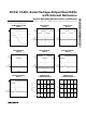
SCLK
DIN
CS
MOSI
SCK
5V
I/O
SPI/QSPI
PORT
SS
MAX5230
MAX5231
Figure 4. SPI/QSPI Interface Connections
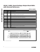
SCLK
DIN
CS
SK
SO
I/O
MICROWIRE
PORT
MAX5230
MAX5231
Figure 5. Connections for MICROWIRE