
Instruction Manual


Digital Feedthrough
Digital feedthrough is noise generated on the DAC’s
output when any digital input transitions. Proper board
layout and grounding significantly reduce this noise,
but there is always some feedthrough caused by the
DAC itself.
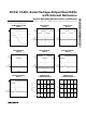
Unipolar Output
Figure 7 shows the MAX5230/MAX5231 configured for
unipolar, rail-to-rail operation. The MAX5231 produces
a 0 to 4.095V output, while the MAX5230 produces 0 to
2.0475V output. Table 4 lists the unipolar output codes.
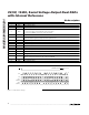
Digital Calibration and
Threshold Selection
Figure 8 shows the MAX5230/MAX5231 in a digital cali-
bration application. With a bright light value applied to
the photodiode (on), the DAC is digitally ramped until it
trips the comparator. The microprocessor (µP) stores
this “high” calibration value. Repeat the process with a
dim light (off) to obtain the dark current calibration. The
µP then programs the DAC to set an output voltage at
the midpoint of the two calibrated values. Applications
include tachometers, motion sensing, automatic read-
ers, and liquid clarity analysis.
Sharing a Common DIN Line
Several MAX5230/MAX5231s may share one common
DIN signal line (Figure 9). In this configuration, the data
bus is common to all devices; data is not shifted through
a daisy-chain. The SCLK and DIN lines are shared by all
devices, but each IC needs its own dedicated CS line.
Daisy-Chaining Devices
Any number of MAX5230/MAX5231s can be daisy-
chained by connecting the serial data output (DOUT) of
one device to the digital input (DIN) of the following
device in the chain (Figure 10).
MAX5230/MAX5231
3V/5V, 12-Bit, Serial Voltage-Output Dual DACs
with Internal Reference
______________________________________________________________________________________ 15
Table 4. Unipolar Code Table
DAC CONTENTS ANALOG OUTPUT (V)
MSB LSB MAX5230 MAX5231
1111 1111 1 111 (0) 2.04750 4.0950
1000 0000 0 001 (0) 1.02425 2.0485
1000 0000 0 000 (0) 1.02375 2.0475
0111 1111 1 111 (0) 1.02325 2.0465
0000 0000 001 (0) 0.00050 0.0010
0000 0000 0 000 (0) 0 0
DAC_
MAX5230
MAX5231
REF
REF
V
DD
5V/3V
GAIN = 1.6384V/V
OUT_
OS_
121kΩ
77.25kΩ
1kΩ
AGND DGND
Figure 7. Unipolar Output Circuit (Rail-to-Rail)
DAC_
MAX5230
MAX5231
REF
REF
V
DD
V
OUT
5V/3V
OUT_
PHOTODIODE
OS_
V+
V+
V-
121kΩ
77.25kΩ
1kΩ
R
PULLDOWN
AGND DGND
Figure 8. Digital Calibration