
Manual


MAX5477/MAX5478/MAX5479
Dual, 256-Tap, Nonvolatile, I
2
C-Interface,
Digital Potentiometers
12 ______________________________________________________________________________________
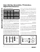
ADDRESS BYTE COMMAND BYTE DATA BYTE
1 2 3 4 5 6 7 8 9 1011121314151617 18 1920 212223242526 27
SCL CYCLE
NUMBER
START
(S)
A6 A5 A4 A3 A2 A1 A0
ACK
(A)
TX NV V R3 R2 R1 R0
ACK
(A)
D7 D6 D5 D4 D3 D2 D1 D0
ACK
(A)
STOP
(P)
NOTES
VREG
0101A2A1A00 00010001 D7D6D5D4D3D2D1D0
NVREG
0101A2A1A00 00100001 D7D6D5D4D3D2D1D0
NVREGxVREG
0101A2A1A00 01100001 D7D6D5D4D3D2D1D0
VREGxNVREG
0101A2A1A00 01010001 D7D6D5D4D3D2D1D0
WIPER A
ONLY
VREG
0101A2A1A00 00010010 D7D6D5D4D3D2D1D0
NVREG
0101A2A1A00 00100010 D7D6D5D4D3D2D1D0
NVREGxVREG
0101A2A1A00 01100010 D7D6D5D4D3D2D1D0
VREGxNVREG
0101A2A1A00 01010010 D7D6D5D4D3D2D1D0
WIPER B
ONLY
VREG
0101A2A1A00 00010011 D7D6D5D4D3D2D1D0
NVREG
0101A2A1A00 00100011 D7D6D5D4D3D2D1D0
NVREGxVREG
0101A2A1A00 01100011 D7D6D5D4D3D2D1D0
VREGxNVREG
0101A2A1A00 01010011 D7D6D5D4D3D2D1D0
WIPERS
A AND B
Table 2. Command Byte Summary
Standby
The MAX5477/MAX5478/MAX5479 feature a low-power
standby mode. When the device is not being pro-
grammed, it enters into standby mode and supply cur-
rent drops to 500nA (typ).
Applications Information
The MAX5477/MAX5478/MAX5479 are ideal for circuits
requiring digitally controlled adjustable resistance,
such as LCD contrast control (where voltage biasing
adjusts the display contrast), or for programmable fil-
ters with adjustable gain and/or cutoff frequency.
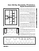
Positive LCD Bias Control
Figures 9 and 10 show an application where the
MAX5477/MAX5478/MAX5479 provide an adjustable,
positive LCD bias voltage. The op amp provides buffer-
ing and gain to the resistor-divider network made by
the potentiometer (Figure 9) or by a fixed resistor and a
variable resistor (see Figure 10).
Programmable Filter
Figure 11 shows the MAX5477/MAX5478/MAX5479 in a
1st-order programmable application filter. Adjust the
gain of the filter with R
2
, and set the cutoff frequency
with R
3
. Use the following equations to calculate the
gain (A) and the -3dB cutoff frequency (f
C
):
A
R
R
f
RC
C
=+
=
××
1
1
2
1
2
3
π
V
OUT
30V
5V
W_
H_
L_
MAX5477
MAX5478
MAX5479
MAX480
V
OUT
30V
5V
W_
H_
L_
MAX5477
MAX5478
MAX5479
MAX480
Figure 9. Positive LCD Bias Control Using a Voltage-Divider
Figure 10. Positive LCD Bias Control Using a Variable Resistor