
Owner manual


address bits and a read/write bit (R/W). When idle, the
device continuously waits for a START condition fol-
lowed by its slave address. When the device recog-
nizes its slave address, it acquires the data and
executes the command. The first 5 bits (MSBs) of the
slave address have been factory programmed and are
always 01100. Connect A1 and A0 to V
DD
or GND to
program the remaining 2 bits of the slave address. Set
the least significant bit (LSB) of the address byte (R/W)
to zero to write to the MAX5548. After receiving the
address, the MAX5548 (slave) issues an acknowledge
by pulling SDA low for one clock cycle. I
2
C read com-
mands (R/W = 1) are not acknowledged by the
MAX5548.
Write Cycle
The write command requires 27 clock cycles. In write
mode (R/W = 0), the command/data byte that follows
the address byte controls the MAX5548 (Table 3). The
registers update on the rising edge of the 26th SCL
pulse. Prematurely aborting the write cycle does not
update the DAC. See Table 4 for a command summary.
SPI Compatibility (SPI/
I2C
= V
DD
)
The MAX5548 is compatible with the 3-wire SPI serial
interface (Figure 6). This interface mode requires three
inputs: chip-select (CS), data clock (SCLK), and data in
(DIN). Drive CS low to enable the serial interface and
clock data synchronously into the shift register on each
SCLK rising edge.
The MAX5548 requires 16 clock cycles to clock in 6
command bits (C5–C0) and 8 data bits (D7–D0) and S1
= S0 = 0 (Figure 7). After loading data into the shift regis-
ter, drive CS high to latch the data into the appropriate
DAC register and disable the serial interface. Keep CS
low during the entire serial data stream to avoid corrup-
tion of the data. See Table 4 for a command summary.
Shutdown Mode
The MAX5548 has a software shutdown mode that
reduces the supply current to less than 1µA. Shutdown
mode disables the DAC outputs. The serial interface
remains active in shutdown. This provides the flexibility
to update the registers while in shutdown. Recycling the
power supply resets the device to the default settings.
MAX5548
Dual, 8-Bit, Programmable, 30mA
High-Output-Current DAC
______________________________________________________________________________________ 11
12 8 9
ACKNOWLEDGE
SCL
S
SDA
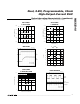
Figure 5. Acknowledge Condition
S
T
A
R
T
ADDRESS
BYTE
R/ W**
COMMAND/DATA BYTE DATA BYTE*
S
T
O
P
Master
SDA
S01100
A
1
A0 0 C5 C4 C3 C2 C1 C0 D7 D6 D5 D4 D3 D2 D1 D0 S1** S0** P
Slave
SDA
A
C
K
ACK
A
C
K
Table 3. Write Operation
*S1 and S0 are subbits. Set S1 and S0 to zero for proper 8-bit operation.
**Read operation not supported.