
Owner manual


MAX5548
Applications Information
Daisy Chaining (SPI/
I2C
= V
DD
)
In standard SPI-/QSPI™-/MICROWIRE™-compatible
systems, a microcontroller (µC) communicates with its
slave devices through a 3- or 4-wire serial interface.
The typical interface includes a chip-select signal (CS),
a serial clock (SCLK), a data input signal (DIN), and
sometimes a data signal output (DOUT). In this system,
the µC allots an independent slave-select signal (SS_)
to each slave device so that they can be addressed
individually. Only the slaves with their CS inputs assert-
ed low acknowledge and respond to the activity on the
serial clock and data lines. This is simple to implement
when there are very few slave devices in the system.
An alternative method is daisy chaining. Daisy chain-
ing, in serial-interface applications, is the method of
propagating commands through devices connected in
series (see Figure 8).
Daisy chain devices by connecting the DOUT of one
device to the DIN of the next. Connect the SCLK of all
devices to a common clock and connect the CS of all
devices to a common slave-select line. Data shifts out of
DOUT 16.5 clock cycles after it is shifted into DIN on the
falling edge of SCLK. In this configuration, the µC only
needs three signals (SS, SCK, and MOSI) to control all of
the slaves in the network. The SPI-/QSPI-/MICROWIRE-
compatible serial interface normally works at up to
10MHz, but must be slowed to 5MHz if daisy chaining.
DOUT is high impedance when CS is high.
Dual, 8-Bit, Programmable, 30mA
High-Output-Current DAC
12 ______________________________________________________________________________________
1 2 3 4 5 6 7 8 9 10111213141516
D5 D4 D3 D2 D1 D0 S1 S0C3 C2
SCLK
DIN
CS
C5
C4
C1 C0
D7 D6
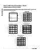
Figure 7. SPI-Interface Format
QSPI is a trademark of Motorola, Inc.
MICROWIRE is a trademark of National Semiconductor Corp.
t
CSW
t
CS1
t
CSD
t
CSH
LSB
t
DO1
t
CL
t
CP
t
CH
t
DH
t
DS
MSB
MSB
t
CSS
t
CSO
CS
SCLK
DIN
DOUT
t
CSE
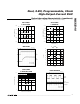
Figure 6. SPI-Interface Timing Diagram