
Manual


MAX5556–MAX5559
Left/Right Clock Input (LRCLK)
LRCLK is the left/right clock input signal for the 3-wire
interface and sets the sample frequency (f
S
). On the
MAX5556, drive LRCLK low to direct data to OUTL or
LRCLK high to direct data to OUTR (Figure 4). On the
MAX5557/MAX5558/MAX5559, drive LRCLK high to
direct data to OUTL or LRCLK low to direct data to
OUTR (Figures 5, 6, 7). LRCLK is internally resampled
on each SCLK rising edge. The MAX5556–MAX5559
accept data at LRCLK audio sample rates from 2kHz to
50kHz.
Master Clock (MCLK)
MCLK accepts the master clock signal from an external
clocking device and is used to derive internal clock fre-
quencies. Set the MCLK/LRCLK ratio to 256, 384, or
512 to achieve the internal serial clock frequencies list-
ed in Table 1. Table 2 details the MCLK/LRCLK ratios
for three sample audio rates.
The MAX5556–MAX5559 detect the MCLK/LRCLK ratio
during the initialization sequence by counting the num-
ber of MCLK transitions during a single LRCLK period.
MCLK, SCLK, and LRCLK must be synchronous sig-
nals.
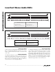
Data Formats
MAX5556 I
2
S Left-Justified Data Format
The MAX5556 accepts data with an I
2
S left-justified
data format, accepting up to 24 bits of data. SDATA
accepts data in two’s complement format with the MSB
first. The MSB is valid on the second SCLK rising edge
after LRCLK transitions low to high or high to low
(Figure 4). Drive LRCLK low to direct data to OUTL.
Drive LRCLK high to direct data to OUTR. The number
of SCLK pulses with LRCLK high or low determines the
number of bits transferred per sample. If fewer than 24
bits of data are written, the remaining LSBs are set to 0.
If more than 24 bits are written, any bits after the LSB
are ignored.
The MAX5556 accepts up to 24 bits of data in external
serial clock mode or when the MCLK/LRCLK ratio is
384 (internal serial clock = 48 x f
S
) in internal serial
clock mode. The DAC also accepts 16 bits of data in
internal serial clock mode when the MCLK/LRCLK ratio
is 256 or 512 (internal serial clock = 32 x f
S
).
MAX5557 Left-Justified Data Format
The MAX5557 accepts data with a left-justified data for-
mat, allowing for up to 24 bits of data. SDATA accepts
data in two’s complement format with the MSB first. The
MSB is valid on the first SCLK rising edge after LRCLK
transitions low to high or high to low (Figure 5). Drive
LRCLK high to direct data to OUTL. Drive LRCLK low to
direct data to OUTR. The number of SCLK pulses with
LRCLK high or low determines the number of bits trans-
ferred per sample. If fewer than 24 bits of data are writ-
ten, the remaining LSBs are set to 0. If more than 24
bits are written, the bits after the LSB are ignored.
The MAX5557 accepts up to 24 bits of data in external
serial clock mode and internal serial clock mode.
Program the MCLK/LRCLK ratio to 384 to operate the
internal serial clock at 48 x f
S
. Program the
MCLK/LRCLK ratio to 256 or 512 to operate the internal
serial clock at 64 x f
S
.
MAX5558 16-Bit Right-Justified Data Format
The MAX5558 operates from a 16-bit right-justified data
format. The LSB is valid on the final SCLK rising edge
prior to LRCLK transitioning low to high or high to low
(Figure 6). In external serial clock mode, the MAX5558
requires a minimum of 32 SCLK cycles per LRCLK peri-
od (16 SCLK cycles with LRCLK low and 16 SCLK
cycles with LRCLK high). Drive LRCLK high to direct
data to OUTL. Drive LRCLK low to direct data to OUTR.
Any additional SDATA bits prior to the MSB are ignored.
Low-Cost Stereo Audio DACs
12 _______________________________________________________________________________________
Table 1. Internal and External Clock
Frequencies
INTERNAL SERIAL
CLOCK FREQUENCY
PART
M C L K /L R C L K
= 2 5 6 O R 51 2
M C L K /L R C L K
= 3 8 4
EXTERNAL
SERIAL
CLOCK
FREQUENCY
MAX5556 32 x f
S
48 x f
S
User defined
(Figure 4)
MAX5557 64 x f
S
48 x f
S
User defined
(Figure 5)
MAX5558 32 x f
S
48 x f
S
User defined
(Figure 6)
MAX5559 64 x f
S
48 x f
S
User defined
(Figure 7)
Table 2. MCLK/LRCLK Ratios
MCLK (MHz)
LRCLK
(kHz)
MCLK/LRCLK
= 256
MCLK/LRCLK
= 384
MCLK/LRCLK
= 512
32 8.1920 12.2880 16.3840
44.1 11.2896 16.9344 22.5792
48 12.2880 18.4320 24.5760