
Manual


MAX5556–MAX5559
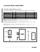
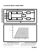
Detailed Description
The MAX5556–MAX5559 stereo audio sigma-delta DACs
offer a complete stereo digital-to-analog system for con-
sumer audio applications. The MAX5556–MAX5559 fea-
ture built-in digital interpolation/filtering, sigma-delta
digital-to-analog conversion and analog output filters
(Figure 2). Control logic and mute circuitry minimize
audible pops and clicks during power-up, power-down,
and whenever invalid clock conditions occur.
These stereo audio DACs receive input data over a 3-
wire interface that supports up to 24 bits of left-justified,
right-justified, or I
2
S-compatible audio data. The
MAX5556 accepts left-justified I
2
S data, up to 24 bits.
The MAX5557 accepts left-justified data, up to 24 bits.
The MAX5558 accepts right-justified 16-bit data. The
MAX5559 accepts right-justified 18-bit data. These
DACs also support a wide range of sample rates from
2kHz to 48kHz. Direct analog output data is routed to
the right or left output by driving LRCLK high or low.
See the
Clock and Data Interface
section.
The MAX5556–MAX5559 support MCLK/LRCLK ratios
of 256, 384, or 512. These devices allow a change to
the clock speed ratio without causing glitches on the
analog outputs by internally muting the audio during
invalid clock conditions. The internal mute function
ramps down the audio amplitude and forces the analog
outputs to a 2.4V quiescent voltage immediately upon
clock loss or change of ratio. A soft-start routine is then
engaged when a valid clock ratio is re-established, pro-
ducing clickless and popless continuous operation.
The MAX5556–MAX5559 operate from a +4.75V to
+5.5V analog supply and feature +87dB dynamic
range with total harmonic distortion typically below
-87dB.
Interpolator
The digital interpolation filter eliminates images of the
baseband audio signal that exist at multiples of the input
sample rate (f
S
). The resulting upsampled frequency
spectrum has images of the input signal at multiples of 8
x f
S
. An additional upsampling sinc filter further reduces
upsampling images up to 64 x f
S
. These images are ulti-
mately removed through the internal analog lowpass filter
and the external analog output filter.
Sigma-Delta Modulator/DAC
The MAX5556–MAX5559 use a multibit sigma-delta DAC
with an oversampling ratio (OSR) of 64 to achieve a wide
dynamic range. The sigma-delta modulator accepts a 3-
bit data stream from the interpolation filter at a rate of 64
x f
S
(f
S
= LRCLK frequency) and provides an analog volt-
age representation of that data stream.
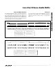
Pin Description
PIN NAME FUNCTION
1 SDATA
Serial Audio Data Input. Data is clocked into the MAX5556–MAX5559 on the rising edge of the
internal or external SCLK. Data is input in two’s complement format, MSB first. The state of LRCLK
determines whether data is directed to OUTL or OUTR.
2 SCLK External Serial Clock Input. Data is strobed on the rising edge of SCLK.
3 LRCLK
Left-/Right-Channel Select Clock. For the MAX5556, drive LRCLK low to direct data to OUTL or
LRCLK high to direct data to OUTR. For the MAX5557/MAX5558/MAX5559, drive LRCLK high to
direct data to OUTL or LRCLK low to direct data to OUTR.
4 MCLK Master Clock Input. The MCLK/LRCLK ratio must equal to 256, 384, or 512.
5 OUTR Right-Channel Analog Output
6 GND Ground
7V
DD
Power-Supply Input. Bypass V
DD
to GND with a 0.1µF capacitor in parallel with a 4.7µF capacitor as
close to V
DD
as possible. Place the 0.1µF capacitor closest to V
DD.
8 OUTL Left-Channel Analog Output
Low-Cost Stereo Audio DACs
_______________________________________________________________________________________
7