9-3148; Rev 1; 5/04 KIT ATION EVALU LE B A IL A AV 32-Channel, 16-Bit, Voltage-Output DACs with Serial Interface The MAX5732–MAX5735 are 32-channel, 16-bit, voltageoutput, digital-to-analog converters (DACs). All devices accept a 3V external reference input. The devices include an internal offset DAC that allows all the outputs to be offset and a ground-sensing function, allowing output voltages to be referenced to a remote ground.
MAX5732–MAX5735 32-Channel, 16-Bit, Voltage-Output DACs with Serial Interface ABSOLUTE MAXIMUM RATINGS AVCC to VSS, AGND, DGND, REFGND ..................-0.3V to +12V VSS to AGND, DGND................................................-6V to +0.3V AVDD, DVDD to AGND, DGND, REFGND.................-0.3V to +6V AGND to DGND.....................................................-0.3V to +0.3V REF to AGND, DGND, REFGND...............-0.3V to the lower of (AVDD + 0.3V) and +6V REFGND to AGND..........................
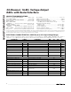
2-Channel, 16-Bit, Voltage-Output DACs with Serial Interface (AVCC = +5.25V to +5.5V (Note 1), AVDD = +5V ±5%, DVDD = +2.7V to AVDD, VSS = AGND = DGND = REFGND = GS = 0, VREF = +3.0V, RL = ∞, CL = 50pF referenced to ground, TA = TMIN to TMAX, unless otherwise noted. Typical values are at TA = +25°C.) PARAMETER SYMBOL CONDITIONS MIN TYP MAX UNITS Capacitive Load to Ground 50 100 pF DC Output Impedance 0.
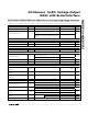
MAX5732–MAX5735 32-Channel, 16-Bit, Voltage-Output DACs with Serial Interface ELECTRICAL CHARACTERISTICS—MAX5733 (0 to +10V Output Voltage Range) (AVCC = +10.5V to +11V, AVDD = 5V ±5%, DVDD = +2.7V to AVDD, VSS = AGND = DGND = REFGND = GS = 0, VREF = +3.0V, RL = ∞, CL = 50pF referenced to ground, TA = TMIN to TMAX, unless otherwise noted. Typical values are at TA = +25°C.
32-Channel, 16-Bit, Voltage-Output DACs with Serial Interface (AVCC = +10.5V to +11V, AVDD = 5V ±5%, DVDD = +2.7V to AVDD, VSS = AGND = DGND = REFGND = GS = 0, VREF = +3.0V, RL = ∞, CL = 50pF referenced to ground, TA = TMIN to TMAX, unless otherwise noted. Typical values are at TA = +25°C.) PARAMETER SYMBOL CONDITIONS MIN TYP MAX UNITS DIGITAL INPUTS (CS, SCLK, DIN, LDAC, CLR, DSP) Input-Voltage High VIH DVDD = +2.7V to +3.6V DVDD = +4.75V to +5.
MAX5732–MAX5735 32-Channel, 16-Bit, Voltage-Output DACs with Serial Interface ELECTRICAL CHARACTERISTICS—MAX5734 (-2.5V to +7.5V Output Voltage Range) (AVCC = +7.75V to +8.25V, AVDD = +5V ±5%, DVDD = +2.7V to AVDD, VSS = -2.75V to -3.25V, AGND = DGND = REFGND = GS = 0, program the offset DAC to 4000hex. VREF = +3.0V, RL = ∞, CL= 50pF referenced to ground, TA = TMIN to TMAX, unless otherwise noted. Typical values are at TA = +25°C.
32-Channel, 16-Bit, Voltage-Output DACs with Serial Interface (AVCC = +7.75V to +8.25V, AVDD = +5V ±5%, DVDD = +2.7V to AVDD, VSS = -2.75V to -3.25V, AGND = DGND = REFGND = GS = 0, program the offset DAC to 4000hex. VREF = +3.0V, RL = ∞, CL= 50pF referenced to ground, TA = TMIN to TMAX, unless otherwise noted. Typical values are at TA = +25°C.) PARAMETER SYMBOL CONDITIONS MIN TYP MAX UNITS DIGITAL INPUTS (CS, SCLK, DIN, LDAC, CLR, DSP) Input-Voltage High VIH DVDD = +2.7V to +3.6V DVDD = +4.
MAX5732–MAX5735 32-Channel, 16-Bit, Voltage-Output DACs with Serial Interface ELECTRICAL CHARACTERISTICS—MAX5735 (-5V to +5V Output Voltage Range) (AVCC = +5.25V to +5.5V, AVDD = +5V ±5%, DVDD = +2.7V to AVDD, VSS = -5.25V to -5.5V, AGND = DGND = REFGND = GS = 0, program the offset DAC to 8000hex. VREF = +3.0V, RL = ∞, CL = 50pF referenced to ground, TA = TMIN to TMAX, unless otherwise noted. Typical values are at TA = +25°C.
32-Channel, 16-Bit, Voltage-Output DACs with Serial Interface (AVCC = +5.25V to +5.5V, AVDD = +5V ±5%, DVDD = +2.7V to AVDD, VSS = -5.25V to -5.5V, AGND = DGND = REFGND = GS = 0, program the offset DAC to 8000hex. VREF = +3.0V, RL = ∞, CL = 50pF referenced to ground, TA = TMIN to TMAX, unless otherwise noted. Typical values are at TA = +25°C.
MAX5732–MAX5735 32-Channel, 16-Bit, Voltage-Output DACs with Serial Interface TIMING CHARACTERISTICS—DVDD = +4.75V to +5.25V (Figures 2 and 3, AVDD = +4.75V to +5.25V, DVDD = +4.75V to +5.25V, AGND = DGND = REFGND = GS = 0, TA = TMIN to TMAX, unless otherwise noted. Typical values are at TA = +25°C.
32-Channel, 16-Bit, Voltage-Output DACs with Serial Interface DIFFERENTIAL NONLINEARITY vs. INPUT CODE 4 0.3 2.0 INL (LSB) 2 0.1 0 1.0 0 -0.1 0.5 0 -0.2 0 10k 20k 30k 40k 50k 60k 70k 0 10k 20k 30k 40k 50k 60k -40 70k -15 10 35 INPUT CODE INPUT CODE TEMPERATURE (°C) WORST-CASE DNL vs. TEMPERATURE ZERO-SCALE ERROR vs. TEMPERATURE FULL-SCALE ERROR vs. TEMPERATURE 0.15 0.10 0.05 4 3 2 -15 10 35 60 85 85 MAX5732 toc06 3.0 2.5 2.0 1.
32-Channel, 16-Bit, Voltage-Output DACs with Serial Interface MAX5732–MAX5735 Typical Operating Characteristics (continued) (AVCC = +10.5V ±5%, AVDD = +5V ±5%, DVDD = +5V, VSS = AGND = DGND = REFGND = GS = 0, VREF = +3.000V, RL = ∞, CL = 50pF referenced to ground, output gain = 2.5, TA = TMIN to TMAX, unless otherwise noted. Typical values are at TA = +25°C).
32-Channel, 16-Bit, Voltage-Output DACs with Serial Interface PIN NAME 1, 42, 48 AVCC Output-Amplifier Positive Supply Input. Bypass to VSS with a 0.1µF capacitor. FUNCTION 2 OUT9 DAC9 Buffered Analog Output Voltage 3 OUT8 DAC8 Buffered Analog Output Voltage 4 OUT7 DAC7 Buffered Analog Output Voltage 5 N.C. 6 OUT6 No Connection. Internally connected. Do not make any connections to N.C.
32-Channel, 16-Bit, Voltage-Output DACs with Serial Interface MAX5732–MAX5735 Pin Description (continued) PIN NAME 40 OUT22 DAC22 Buffered Analog Output Voltage 41 OUT21 DAC21 Buffered Analog Output Voltage 43 OUT20 DAC20 Buffered Analog Output Voltage 44 OUT19 DAC19 Buffered Analog Output Voltage 45 OUT18 DAC18 Buffered Analog Output Voltage 46 OUT17 DAC17 Buffered Analog Output Voltage 47 OUT16 DAC16 Buffered Analog Output Voltage 51 OUT15 DAC15 Buffered Analog Output Voltage 52
32-Channel, 16-Bit, Voltage-Output DACs with Serial Interface MAX5732–MAX5735 AVCC INPUT REGISTER DAC0 REGISTER DAC0 OUT0 VSS AVCC INPUT REGISTER DAC1 REGISTER DAC1 OUT1 VSS AVCC INPUT REGISTER DAC_ REGISTER DAC_ OUT_ VSS AVCC INPUT REGISTER DAC30 REGISTER DAC30 OUT30 VSS AVCC INPUT REGISTER DAC31 REGISTER DAC31 OUT31 VSS AVCC OFFSET DAC REGISTER INPUT REGISTER OFFSET DAC VSS AGND POWER MANAGEMENT AVDD DVDD GS REF DOUT CLR LDAC DSP DIN SCLK CS DIGITAL CONTROL LOGIC MA
MAX5732–MAX5735 32-Channel, 16-Bit, Voltage-Output DACs with Serial Interface Detailed Description range; the MAX5734 has a -2.5V to +7.5V output range; and the MAX5735 has a -5V to +5V output range. The MAX5732–MAX5735 are 32-channel, 16-bit, voltage-output DACs (Figure 1). The devices accept a 3V external reference input at REF. An internal offset DAC allows all outputs to be offset (see Table 1).
32-Channel, 16-Bit, Voltage-Output DACs with Serial Interface PART NUMBER D16 D15 D14 D13 D12 D11 D10 D9 D8 D7 D6 D5 D4 D3 D2 D1 D0 MAX5732 0 0 0 0 0 0 0 0 0 0 0 0 0 0 0 0 0 MAX5733 0 0 0 0 0 0 0 0 0 0 0 0 0 0 0 0 0 MAX5734 0 1 0 0 0 0 0 0 0 0 0 0 0 0 0 0 0 MAX5735 1 0 0 0 0 0 0 0 0 0 0 0 0 0 0 0 0 Note: For the MAX5732, the maximum code for the offset DAC is 16384.
MAX5732–MAX5735 32-Channel, 16-Bit, Voltage-Output DACs with Serial Interface A software command can also activate the LDAC operation. To activate LDAC by software, set control bits C2, C1, and C0 = 010, address bits A5–A0 = 111111, and all data bits to don’t care. See Table 3 for the data format. This operation updates all DAC outputs. Note: The software load DAC does not affect the offset DAC.
32-Channel, 16-Bit, Voltage-Output DACs with Serial Interface ADDRESS BITS A5 A4 A3 A2 A1 A0 CONTROL FUNCTION ADDRESS BITS A5 A4 A3 A2 A1 A0 CONTROL FUNCTION 0 0 0 0 0 0 DAC0 1 0 0 0 1 0 Command reserved; do not use. 0 0 0 0 0 1 DAC1 1 0 0 0 1 1 Command reserved; do not use. 0 0 0 0 1 0 DAC2 1 0 0 1 0 0 Command reserved; do not use. 0 0 0 0 1 1 DAC3 1 0 0 1 0 1 Command reserved; do not use. 0 0 1 1 0 Command reserved; do not use.
MAX5732–MAX5735 32-Channel, 16-Bit, Voltage-Output DACs with Serial Interface Table 8. Configuration-Register Data Format 16 DATA BITS D15 D14 D13 D12 D11 D10 D9 D8 D7 D6 D5 D4 D3 D2 D1 D0 ERRF SING GLT DT SHDN X X X X X X X X X X X X = Don’t care. Table 9. Configuration-Register Commands DATA BIT D15 D14 D13 D12 NAME DESCRIPTION ERRF Error flag; ERRF goes logic-high when an invalid command is attempted.
32-Channel, 16-Bit, Voltage-Output DACs with Serial Interface MAX573_ DIN(0) SCLK DOUT(0) CS CONTROLLER DEVICE 1 DSP MAX573_ DIN(1) SCLK DOUT(1) CS Daisy Chain Operation DSP Any number of the MAX5732–MAX5735 devices can be daisy chained by connecting the DOUT of one device to the DIN of another device in a chain. All devices must be in SING = 0 mode. Connecting the CS inputs of all devices together eliminates the need to issue NOP commands to devices early in the chain (see Figure 4).
MAX5732–MAX5735 32-Channel, 16-Bit, Voltage-Output DACs with Serial Interface DIN(0) W WD2 W WD1 W WD0 R XX R XX R XX X XX X XX X XX W WD2 W WD1 W WD0 R XX R XX R RD0 X XX X XX W WD2 W WD1 W WD0 R XX R RD1 R RD0 X XX R RD2 R RD1 R RD0 CS DOUT(0) DOUT(1) W WD2 DOUT(2) W WD1 W WD0 Figure 5. Example 1 of a Daisy-Chain Data Sequence W/WD0 = 32-bit word with a write command; WD0 writes data for device 0.
32-Channel, 16-Bit, Voltage-Output DACs with Serial Interface CONTROLLER DEVICE 1 OR 0 DSP Figure 7. Stand-Alone Configuration Shutdown Mode MAX573_ DIN SCLK DOUT CS CONTROLLER DEVICE 1 OR 0 DSP MAX573_ DIN SCLK DOUT CS 1 OR 0 DSP MAX573_ DIN SCLK DOUT CS 1 OR 0 The MAX5732–MAX5735 feature a software-controlled low-power shutdown mode. When bit 11 of the configuration register is a logic high, the analog section of the device is disabled, and the outputs go high impedance.
MAX5732–MAX5735 32-Channel, 16-Bit, Voltage-Output DACs with Serial Interface HVDRV0 DAC0 MAX5732 MAX5733 VOLTAGE REFERENCE DAC31 HVDRV31 14 TO 16 BITS CONTROL ALGORITHM DWDM PIPE DSP 14 TO 16 BITS ADC POSITION OR OPTICAL FEEDBACK VOLTAGE REFERENCE PGA OR FIXED GAIN AMPS MEMS MIRRORS WITH X AND Y CONTROL THIN-FILM FILTER OR PLANAR LIGHT WAVE SEPARATORS WITH OPTICAL LENSES MEMS MIRRORS WITH X AND Y CONTROL DWDM PIPE OPTICAL LENSES AND COLLIMATORS Figure 10.
32-Channel, 16-Bit, Voltage-Output DACs with Serial Interface Additional protection is provided by the MAX5734 glitch-free power-up into the clear state with all DAC outputs set to approximately 0V. Either the serial port or the CLR input can assert the clear function. Power Supplies, Bypassing, Decoupling, and Layout Grounding and power-supply decoupling strongly influence device performance. Digital signals can couple through the reference input, power supplies, and ground connection.
Package Information (The package drawing(s) in this data sheet may not reflect the most current specifications. For the latest package outline information, go to www.maxim-ic.com/packages.) 56L THIN QFN.EPS MAX5732–MAX5735 32-Channel, 16-Bit, Voltage-Output DACs with Serial Interface Maxim cannot assume responsibility for use of any circuitry other than circuitry entirely embodied in a Maxim product. No circuit patent licenses are implied.