
Manual


MAX5886
3.3V, 12-Bit, 500Msps High Dynamic
Performance DAC with Differential LVDS Inputs
______________________________________________________________________________________ 13
between the frequency components located within the
carrier band. The energy at one end of the carrier band
generates IM products with the energy from the oppo-
site end of the carrier band. For single-carrier W-CDMA
modulation, these IMD products are spread 3.84MHz
over the adjacent sideband. Four contiguous W-CDMA
carriers spread their IM products over a bandwidth of
20MHz on either side of the 20MHz total carrier band-
width. In this four-carrier scenario, only the energy in
the first adjacent 3.84MHz side band is considered for
ACLR 1. To measure ACLR, drive the converter with a
W-CDMA pattern. Make sure that the signal is backed
off by the peak-to-average ratio, such that the DAC is
not clipping the signal. ACLR can then be measured
with the ACLR measurement function built into your
spectrum analyzer.
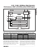
Figure 9 shows the ACLR performance for a single
W-CDMA carrier (f
CLK
= 184.32MHz, f
OUT
= 61.44MHz)
applied to the MAX5886 (including measurement sys-
tem limitations*).
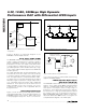
Figure 10 illustrates the ACLR test results for the
MAX5886 with a four-carrier W-CDMA signal at an out-
put frequency of 63.98MHz and sampling frequency of
184.32MHz. Considerable care must be taken to
ensure accurate measurement of this parameter.
Multitone Testing for GSM/EDGE
Applications
The transmitter sections of multicarrier base station
transceiver systems for GSM/EDGE usually present
communication DAC manufacturers with the difficult
task of providing devices with higher resolution, while
simultaneously reducing noise and spurious emissions
over a desired bandwidth.
To specify noise and spurious emissions from base sta-
tions, a GSM/EDGE Tx mask is used to identify the DAC
requirements for these parameters. This mask shows
that the allowable levels for noise and spurious emis-
sions are dependent on the offset frequency from the
transmitted carrier frequency. The GSM/EDGE mask
and its specifications are based on a single active car-
rier with any other carriers in the transmitter being dis-
abled. Specifications displayed in Figure 11 support
per-carrier output power levels of 20W or greater.
Lower output power levels yield less-stringent emission
requirements. For GSM/EDGE applications, the DAC
demands spurious emission levels of less than -80dBc
for offset frequencies ≥6MHz. Spurious products from
the DAC can combine with both random noise and spu-
rious products from other circuit elements. The spuri-
ous products from the DAC should therefore be backed
off by 6dB or more to allow for these other sources and
still avoid signal clipping.
The number of carriers and their signal levels with
respect to the full scale of the DAC are important as
well. Unlike a full-scale sine wave, the inherent nature
of a multitone signal contains higher peak-to-RMS
ratios, raising the prospect for potential clipping, if the
signal level is not backed off appropriately. If a trans-
mitter operates with four/eight in-band carriers, each
*Note that due to their own IM effects and noise limitations, spectrum analyzers introduce ACLR errors, which can falsify the measure-
ment. For a single-carrier ACLR measurement greater than 70dB, these measurement limitations are significant, becoming even more
restricting for multicarrier measurement. Before attempting an ACLR measurement, it is recommended consulting application notes pro-
vided by major spectrum analyzer manufacturers that provide useful tips on how to use their instruments for such tests.
-145
-110
-130
-120
-140
-100
-90
-80
-70
-60
-50
-30
-40
ANALOG OUTPUT POWER (dBm)
-25
3.5MHz/div
f
CENTER
= 61.44MHz
f
CLK
= 184.32Mbps
ACLR = 70dB
Figure 9. ACLR for W-CDMA Modulation, Single Carrier
-145
-120
-130
-140
-90
-80
-70
-60
-50
-25
-40
3.5MHz/div
ANALOG OUTPUT POWER (dBm)
f
CENTER
= 63.98MHz
f
CLK
= 184.32Mbps
ACLR = 63dB
-110
-30
-100
Figure 10. ACLR for W-CDMA Modulation, Four Carriers