
Manual


MAX5886
3.3V, 12-Bit, 500Msps High Dynamic
Performance DAC with Differential LVDS Inputs
14 ______________________________________________________________________________________
individual carrier must be operated at less than
-12dB FS/-18dB FS to avoid waveform clipping.
The noise density requirements (Table 2) for a
GSM/EDGE-based system can again be derived from
the system’s Tx mask. With a worst-case noise level of
-80dBc at frequency offsets of ≥6MHz and a measure-
ment bandwidth of 100kHz, the minimum noise density
per hertz is calculated as follows:
SNR
MIN
= -80dBc - 10 ✕ log
10
(100 ✕ 10
3
Hz)
SNR
MIN
= -130dBc/Hz
Since random DAC noise adds to both the spurious tones
and to random noise from other circuit elements, it is rec-
ommended reducing the specification limits by about
10dB to allow for these additional noise contributions
while maintaining compliance with the Tx mask values.
Other key factors in selecting the appropriate DAC for
the Tx path of a multicarrier GSM/EDGE system is the
converter’s ability to offer superior IMD and MTPR perfor-
mance. Multiple carriers in a designated band generate
unwanted intermodulation distortion between the individ-
ual carrier frequencies. A multitone test vector usually
consists of several equally spaced carriers, usually four,
with identical amplitudes. Each of these carriers is rep-
resentative of a channel within the defined bandwidth of
interest. To verify MTPR, one or more tones are
removed such that the intermodulation distortion perfor-
mance of the DAC can be evaluated. Nonlinearities
associated with the DAC create spurious tones, some
of which may fall back into the area of the removed
tone, limiting a channel’s carrier-to-noise ratio. Other
spurious components falling outside the band of inter-
est can also be important, depending on the system’s
spectral mask and filtering requirements. Going back to
the GSM/EDGE Tx mask, the IMD specification for adja-
cent carriers varies somewhat among the different GSM
standards. For the PCS1800 and GSM850 standards,
the DAC must meet an average IMD of -70dBc.
Table 3 summarizes the dynamic performance require-
ments for the entire Tx signal chain in a four-carrier
GSM/EDGE-based system and compares the previous-
ly established converter requirements with a new-gen-
eration high dynamic performance DAC.
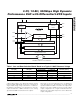
The four-tone MTPR plot in Figure 12 demonstrates the
MAX5886’s excellent dynamic performance. The center
frequency (f
CENTER
= 32MHz) has been removed to
allow detection and analysis of intermodulation or spuri-
ous components falling back into this empty spot from
adjacent channels. The four carriers are observed over
a 12MHz bandwidth and are equally spaced at 1MHz.
Each individual output amplitude is backed off to -12dB
FS. Under these conditions, the DAC yields an MTPR
performance of -78dBc.
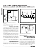
Grounding, Bypassing, and Power-Supply
Considerations
Grounding and power-supply decoupling can strongly
influence the performance of the MAX5886. Unwanted
digital crosstalk may couple through the input, refer-
ence, power supply, and ground connections, affecting
dynamic performance. Proper grounding and power-
NUMBER OF
CARRIERS
CARRIER
POWER LEVEL
(dB FS)
DAC NOISE DENSITY
REQUIREMENT
(dB FS/Hz)
2 -6 -146
4 -12 -152
Table 2. GSM/EDGE Noise Requirements
for Multicarrier Systems
SPECIFICATION
SYSTEM TRANSMITTER
OUTPUT LEVELS
DAC REQUIREMENTS WITH
MARGINS
MAX5886 SPECIFICATIONS
SFDR 80dBc 86dBc 90dBc*
Noise Spectral Density -130dBc/Hz -152dB FS/Hz -154dB FS/Hz
IMD -70dBc -75dBc -85dBc
Carrier Amplitude N/S -12dB FS -12dB FS
Table 3. Summary of Important AC Performance Parameters for Multicarrier GSM/EDGE
Systems
*Measured within a 15MHz window.