
Manual


MAX5886
3.3V, 12-Bit, 500Msps High Dynamic
Performance DAC with Differential LVDS Inputs
______________________________________________________________________________________ 17
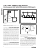
Glitch Energy
A glitch is generated when a DAC switches between
two codes. The largest glitch is usually generated
around the midscale transition, when the input pattern
transitions from 011...111 to 100...000. The glitch ener-
gy is found by integrating the voltage of the glitch at the
midscale transition over time. The glitch energy is usu-
ally specified in pV-s.
Dynamic Performance Parameter
Definitions
Signal-to-Noise Ratio (SNR)
For a waveform perfectly reconstructed from digital sam-
ples, the theoretical maximum SNR is the ratio of the full-
scale analog output (RMS value) to the RMS quantization
error (residual error). The ideal, theoretical minimum can
be derived from the DAC’s resolution (N bits):
SNR
dB
= 6.02
dB
✕ N + 1.76
dB
However, noise sources such as thermal noise, refer-
ence noise, clock jitter, etc., affect the ideal reading;
therefore, SNR is computed by taking the ratio of the
RMS signal to the RMS noise, which includes all spec-
tral components minus the fundamental, the first four
harmonics, and the DC offset.
Spurious-Free Dynamic Range (SFDR)
SFDR is the ratio of RMS amplitude of the carrier fre-
quency (maximum signal components) to the RMS
value of their next-largest distortion component. SFDR
is usually measured in dBc and with respect to the car-
rier frequency amplitude or in dB FS with respect to the
DAC’s full-scale range. Depending on its test condition,
SFDR is observed within a predefined window or
to Nyquist.
Two-/Four-Tone Intermodulation
Distortion (IMD)
The two-tone IMD is the ratio expressed in dBc (or dB
FS) of either input tone to the worst 3rd-order (or high-
er) IMD products. Note that 2nd-order IMD products
usually fall at frequencies that can be easily removed
by digital filtering; therefore, they are not as critical as
3rd-order IMDs. The two-tone IMD performance of the
MAX5886 was tested with the two individual input tone
levels set to at least -6dB FS and the four-tone perfor-
mance was tested according to the GSM model at an
output frequency of 32MHz and amplitude of -12dB FS.
Adjacent Channel Leakage
Power Ratio (ACLR)
Commonly used in combination with W-CDMA, ACLR
reflects the leakage power ratio in dB between the
measured power within a channel relative to its adja-
cent channel. ACLR provides a quantifiable method of
determining out-of-band spectral energy and its influ-
ence on an adjacent channel when a bandwidth-limited
RF signal passes through a nonlinear device.
Chip Information
TRANSISTOR COUNT: 10,629
PROCESS: CMOS