
Manual

MAX5886
3.3V, 12-Bit, 500Msps High Dynamic
Performance DAC with Differential LVDS Inputs
8 _______________________________________________________________________________________
Detailed Description
Architecture
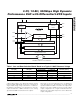
The MAX5886 is a high-performance, 12-bit, current-
steering DAC (Figure 1) capable of operating with clock
speeds up to 500MHz. The converter consists of sepa-
rate input and DAC registers, followed by a current-
steering circuit. This circuit is capable of generating
differential full-scale currents in the range of 2mA to
20mA. An internal current-switching network in combi-
nation with external 50Ω termination resistors convert
the differential output currents into a differential output
voltage with a peak-to-peak output voltage range of
0.1V to 1V. An integrated 1.2V bandgap reference, con-
trol amplifier, and user-selectable external resistor
determine the data converter’s full-scale output range.
Reference Architecture and Operation
The MAX5886 supports operation with the on-chip 1.2V
bandgap reference or an external reference voltage
source. REFIO serves as the input for an external, low-
impedance reference source, and as the output if the
DAC is operating with the internal reference. For stable
operation with the internal reference, REFIO should be
decoupled to AGND with a 0.1µF capacitor. Due to its
limited output drive capability REFIO must be buffered
with an external amplifier, if heavier loading is required.
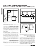
The MAX5886’s reference circuit (Figure 2) employs a
control amplifier, designed to regulate the full-scale
current I
OUT
for the differential current outputs of the
DAC. Configured as a voltage-to-current amplifier, the
output current can be calculated as follows:
I
OUT
= 32 ✕ I
REFIO
- 1 LSB
I
OUT
= 32 ✕ I
REFIO
- (I
OUT
/ 2
12
)
where I
REFIO
is the reference output current (I
REFIO
=
V
REFIO
/R
SET
) and I
OUT
is the full-scale output current of
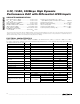
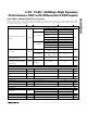
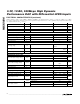
the DAC. Located between FSADJ and DACREF, R
SET
is the reference resistor, which determines the amplifi-
er’s output current for the DAC. See Table 1 for a matrix
of different I
OUT
and R
SET
selections.
Analog Outputs (IOUTP, IOUTN)
The MAX5886 outputs two complementary currents
(IOUTP, IOUTN) that can be operated in a single-ended
or differential configuration. A load resistor can convert
these two output currents into complementary single-
PIN NAME FUNCTION
47 B9N Complementary Data Bit 9
48 B8P Data Bit 8
49 B8N Complementary Data Bit 8
50 B7P Data Bit 7
51 B7N Complementary Data Bit 7
52 B6P Data Bit 6
53 B6N Complementary Data Bit 6
54 B5P Data Bit 5
55 B5N Complementary Data Bit 5
56 B4P Data Bit 4
57 B4N Complementary Data Bit 4
58 B3P Data Bit 3
59 B3N Complementary Data Bit 3
63 B2P Data Bit 2
64 B2N Complementary Data Bit 2
65 B1P Data Bit 1
66 B1N Complementary Data Bit 1
67 B0P Data Bit 0
68 B0N Complementary Data Bit 0
Pin Description (continued)