
Owner manual

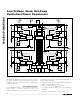

MAX5927/MAX5929
Low-Voltage, Quad, Hot-Swap
Controllers/Power Sequencers
2 _______________________________________________________________________________________
ABSOLUTE MAXIMUM RATINGS
Stresses beyond those listed under “Absolute Maximum Ratings” may cause permanent damage to the device. These are stress ratings only, and functional
operation of the device at these or any other conditions beyond those indicated in the operational sections of the specifications is not implied. Exposure to
absolute maximum rating conditions for extended periods may affect device reliability.
(All voltages referenced to GND, unless otherwise noted.)
IN_ ..........................................................................-0.3V to +14V
GATE_.............................................................-0.3V to (IN_ + 6V)
BIAS (Note 1) .............................................. (V
IN
- 0.3V) to +14V
ON_, STAT_, LIM_ (MAX5927), TIM, MODE,
LATCH (MAX5927), POL (MAX5927)
(Note 1).....................................................-0.3V to (V
IN
+ 0.3V)
SENSE_........................................................-0.3V to (IN_ + 0.3V)
Current into Any Pin..........................................................±50mA
Continuous Power Dissipation (T
A
= +70°C)
24-Pin QSOP (derate 9.5mW/°C above +70°C)............762mW
32-Pin Thin QFN (derate 21.3mW/°C above +70°C) ..1702mW
Operating Temperature Range ...........................-40°C to +85°C
Junction Temperature .....................................................+150°C
Storage Temperature Range .............................-65°C to +150°C
Lead Temperature (soldering, 10s) .................................+300°C
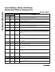
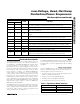
ELECTRICAL CHARACTERISTICS
(V
IN_
= +1V to +13.2V provided at least one supply is larger than or equal to +2.7V and only one supply is > +11.0V, T
A
= -40°C to
+85°C, unless otherwise noted. Typical values are at V
IN1
= 12.0V, V
IN2
= 5.0V, V
IN3
= 3.3V, V
IN4
= 1.0V, V
ON_
= +3.3V, and
T
A
= +25°C.) (Notes 1, 2)
PARAMETER SYMBOL CONDITIONS MIN TYP MAX UNITS
POWER SUPPLIES
IN_ Input Voltage Range V
IN_
At least one V
IN_
≥ +2.7V and only one
V
IN_
> +11.0V
1.0 13.2 V
Supply Current I
Q
I
IN1
+ I
IN2
+ I
IN3
+ I
IN4
, V
ON_
= 2.7V,
V
IN_
= +13.2V, after STAT_ asserts
2.5 5 mA
CURRENT CONTROL
T
A
= +25°C 22.5 25 27.5
LIM_ = GND,
MAX5927/MAX5929
(Note 4)
T
A
= -40°C to +85°C 21.0 27.5
R
LIM_
= 10kΩ (MAX5927) 80 125
Slow-Comparator Threshold
(V
IN_
- V
SENSE_
)
(Note 3)
V
SC,TH
R
LIM_
from LIM_ to GND (MAX5927)
R
LIM_
x 7.5 x
10
-6
+ 25mV
mV
1mV overdrive 3 ms
Slow-Comparator Response Time
(Note 4)
t
SCD
50mV overdrive 130 µs
Fast-Comparator Threshold
(V
IN_
- V
SENSE_
)
V
FC,TH
2 x
V
SC
,
TH
mV
Fast-Comparator Response Time t
FCD
10mV overdrive, from overload condition 200 ns
SENSE_ Input Bias Current I
B SENSE_
V
SENSE_
= V
IN_
0.03 1 µA
MOSFET DRIVER
R
TIM
= 100kΩ 8.0 10.8 13.6
R
TIM
= 4kΩ (minimum value) 0.30 0.4 0.55Startup Period (Note 5) t
START
TIM floating (default) 5 9 14
ms
Note 1: V
IN
is the largest of V
IN1
, V
IN2
, V
IN3
, and V
IN4
.