
Owner manual

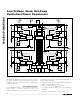

MAX5927/MAX5929
Low-Voltage, Quad, Hot-Swap
Controllers/Power Sequencers
8 _______________________________________________________________________________________
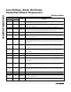
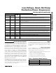
Pin Description
PIN
MAX5927 MAX5929
NAME FUNCTION
1 4 IN1
Channel 1 Supply Input. Connect to a supply voltage from 1V to 13.2V and to one end of
R
SENSE1
. Bypass with a 0.1µF capacitor to ground.
2 5 SENSE1
Channel 1 Current-Sense Input. Connect SENSE1 to the drain of an external MOSFET
and to one end of R
SENSE1
.
3 6 GATE1 Channel 1 Gate-Drive Output. Connect to gate of external N-channel MOSFET.
4 — LIM4
Channel 4 Current-Limit Setting. Connect a resistor from LIM4 to GND to set current-trip
level. Connect to GND for the default 25mV threshold. Do not leave open.
5 7 IN4
Channel 4 Supply Input. Connect to a supply voltage from 1V to 13.2V and to one end of
R
SENSE4
. Bypass with a 0.1µF capacitor to ground.
6 8 SENSE4
Channel 4 Current-Sense Input. Connect SENSE4 to the drain of an external MOSFET
and to one end of R
SENSE4
.
7 9 GATE4 Channel 4 Gate-Drive Output. Connect to gate of external N-channel MOSFET.
8 10 STAT1
Open-Drain Status Signal for Channel 1. STAT1 asserts when hot swap is successful and
t
START
has elapsed. STAT1 deasserts if ON1 is low, or if channel 1 is turned off for any
fault condition.
9 11 STAT2
Open-Drain Status Signal for Channel 2. STAT2 asserts when hot swap is successful and
t
START
has elapsed. STAT2 deasserts if ON2 is low, or if channel 2 is turned off for any
fault condition.
10 12 TIM
Startup Timer Setting. Connect a resistor from TIM to GND to set the startup period.
Leave TIM unconnected for the default startup period of 9ms. R
TIM
must be between
4kΩ and 500kΩ.
11, 20 — N.C. No Connection. Not internally connected.
12 — LATCH
Latch/Autoretry Selection Input. Connect LATCH to GND for autoretry mode after a fault.
Leave LATCH open for latch mode.
13 13 STAT3
Open-Drain Status Signal for Channel 3. STAT3 asserts when hot swap is successful and
t
START
has elapsed. STAT3 deasserts if ON3 is low, or if channel 3 is turned off for any
fault condition.
14 14 STAT4
Open-Drain Status Signal for Channel 4. STAT4 asserts when hot swap is successful and
t
START
has elapsed. STAT4 deasserts if ON4 is low, or if channel 4 is turned off for any
fault condition.
15 15 BIAS
Supply Reference Output. The highest supply is available at BIAS for filtering. Connect a
1nF to 10nF ceramic capacitor from BIAS to GND. No other connections are allowed to
this pin.
16 16 GND Ground
17 17 GATE3 Channel 3 Gate-Drive Output. Connect to gate of external N-channel MOSFET.
18 18 SENSE3
Channel 3 Current-Sense Input. Connect SENSE3 to the drain of an external MOSFET
and to one end of R
SENSE3
.
19 19 IN3
Channel 3 Supply Input. Connect to a supply voltage from 1V to 13.2V and to one end of
R
SENSE3
.