
Owner manual


Detailed Description
The MAX5927/MAX5929 are circuit-breaker ICs for hot-
swap applications where a line card is inserted into a
live backplane. The MAX5927/MAX5929 operate down
to 1V provided one of the inputs is above 2.7V.
Normally, when a line card is plugged in to a live back-
plane, the card’s discharged filter capacitors provide
low impedance that can momentarily cause the main
power supply to collapse. The MAX5927/MAX5929
reside either on the backplane or on the removable
card to provide inrush current limiting and short-circuit
protection. This is achieved by using external N-chan-
nel MOSFETs, external current-sense resistors, and on-
chip comparators. The startup period and current-limit
threshold of the MAX5927/MAX5929 can be adjusted
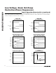
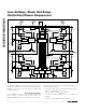
with external resistors. Figure 1 shows the MAX5927/
MAX5929 functional diagram.
The MAX5927 offers four programmable current limits,
selectable fault management mode, and selectable
STAT_ output polarity. The MAX5929 features fixed cur-
rent limits, and a variety of fault management and
STAT_ polarity option combinations.
Mode
The MAX5927/MAX5929 supports three modes of oper-
ation: voltage-tracking, power-sequencing, and inde-
pendent mode. Select the appropriate mode according
to Table 1.
Voltage-Tracking Mode
Connect MODE high to enter voltage-tracking mode.
While in voltage-tracking mode, all channels turn on
and off together. To turn all channels on:
• At least one V
IN_
must exceed V
UVLO
(2.45V) for the
UVLO to startup delay (37.5ms).
• All V
IN_
must exceed V
PWRRDY
(0.95V).
• All V
ON_
must exceed V
ON,TH
(0.875V).
• No faults may be present on any channel.
MAX5927/MAX5929
Low-Voltage, Quad, Hot-Swap
Controllers/Power Sequencers
_______________________________________________________________________________________ 9
MODE OPERATION
High (Connect to BIAS) Voltage tracking
OPEN Power sequencing
GND Independent
Table 1. Operational Mode Selection
PIN
MAX5927 MAX5929
NAME FUNCTION
21 — LIM3
Channel 3 Current-Limit Setting. Connect a resistor from LIM3 to GND to set current-trip
level. Connect to GND for the default 25mV threshold. Do not leave open.
22 20 GATE2 Channel 2 Gate-Drive Output. Connect to gate of external N-channel MOSFET.
23 21 SENSE2
Channel 2 Current-Sense Input. Connect SENSE2 to the drain of an external MOSFET
and to one end of R
SENSE2
.
24 22 IN2
Channel 2 Supply Input. Connect to a supply voltage from 1V to 13.2V and to one end of
R
SENSE2
.
25 — LIM2
Channel 2 Current-Limit Setting. Connect a resistor from LIM2 to GND to set the current-
trip level. Connect to GND for the default 25mV threshold. Do not leave open.
26 23 ON4 On/Off Channel 4 Control Input (see the Mode section)
27 24 ON3 On/Off Channel 3 Control Input (see the Mode section)
28 1 MODE
Mode Configuration Input. Mode is configured according to Table 1 as soon as one of
the IN_ voltages exceeds UVLO and before turning on OUT_ (see the Mode section).
29 — POL STAT Output Polarity Select (See Table 3 and the Status Output Section)
30 2 ON2 On/Off Channel 2 Control Input (See the Mode Section)
31 3 ON1 On/Off Channel 1 Control Input (See the Mode Section)
32 — LIM1
Channel 1 Current-Limit Setting. Connect a resistor from LIM1 to GND to set the current-
trip level. Connect to GND for the default 25mV threshold. Do not leave open.
EP — EP Exposed Pad. Leave EP floating or connect to GND.
Pin Description (continued)